Because of the holidays, TI E2E™ design support forum responses will be delayed from Dec. 25 through Jan. 2. Thank you for your patience.

This thread has been locked.

If you have a related question, please click the "Ask a related question" button in the top right corner. The newly created question will be automatically linked to this question.

LM3402: LM3402 any problems

Part Number: LM3402

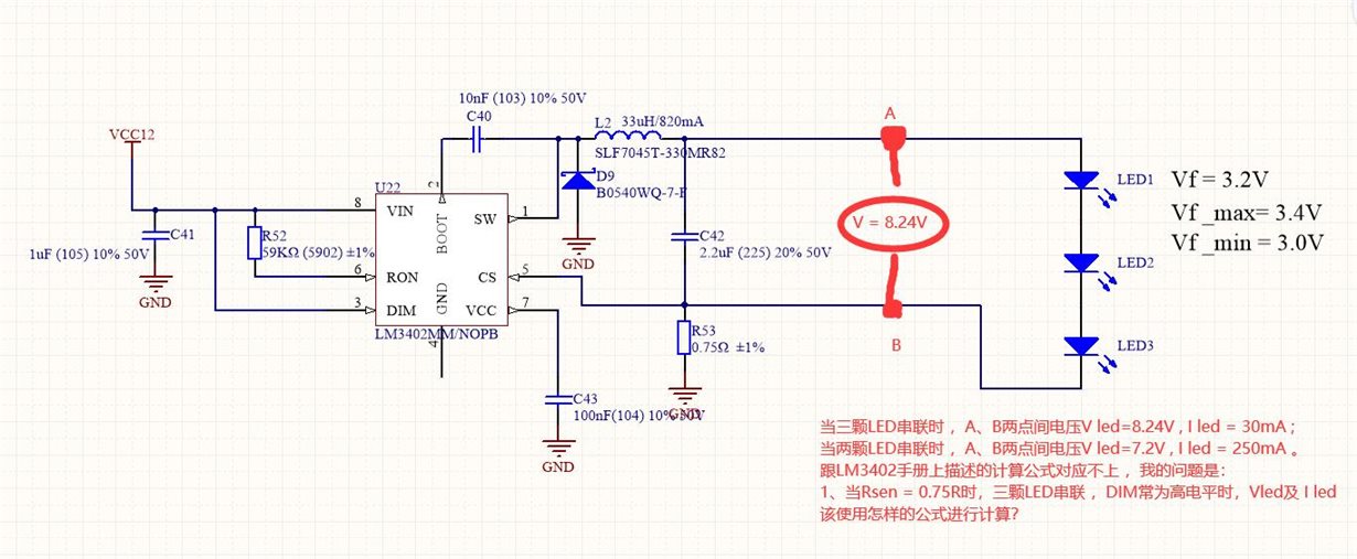
LM3402 Applied schematic diagram(As shown in figure 1)

figure schematic diagram


When DIM= 3.3v, the oscilloscope is used to measure the signals of SW, CS and A respectively:

Figure2 CS(red)and SW(yellow)

As shown in the figure, SW frequency is 1MHz and amplitude is 11.64v


Figure3 A point(red) and SW (yellow)

As shown in the figure, A point V = 8.2V。


According to the current formula in the manual:

calculated If = 212mA  , But by measuring the actual current flowing through the LED serials Current value is 30mA 。


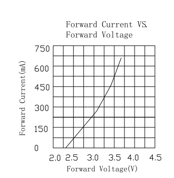
Figure 4 shows the LED voltage ampere curve:


Figure 4     LED voltage-ampere curve 


My question:

  1. When DIM= 3.3v, what determines the frequency of SW point? What's the formula?
  2. The CS end is described as 200mV in the manual, but the actual measurement is an approximate triangular wave with the same frequency as SW. It should be abnormal according to the manual, so what is the problem?
  3. The actual measured current flowing through the LED is only 30mA, which should be calculated as 212mA according to the formula. What's wrong with me?


I hope you can provide help as soon as possible, thank you!

Meanwhile, I hope USA will be healthy and good luck!

  • Hello,

    Note that DIM abs max is 7V show it cannot be connect as the schematic shows.  You state it is a 3.3V which is fine.

    My question:

    1. When DIM= 3.3v, what determines the frequency of SW point? What's the formula?       When dim is 3.3V the output should regulate to the designed current which would be 0.2V/0.75*ohm = 0.212A for the valley current.  The average current will be 0.212A + 0.076A/2 = 0.250A
    2. The CS end is described as 200mV in the manual, but the actual measurement is an approximate triangular wave with the same frequency as SW. It should be abnormal according to the manual, so what is the problem?        It should be a triangle waveform with a DC offset and same as the switching frequency, ramping up when the MOSFET is on and ramping down when the MOSFET is off.
    3. The actual measured current flowing through the LED is only 30mA, which should be calculated as 212mA according to the formula. What's wrong with me?       What I believe is happening is you are running into minimum off time.  I calculate your on time and duty cycle and the off time ends up right at the minimum.  Try changing Ron to a higher value, maybe 100 Kohm.  This will change your average current to a higher value, at 100 Kohm it will go to 0.276A.  You can also try running the input at a higher voltage to see if it starts regulating correct.

    Best Regards,