


Hello everone ,
Sorry for my question I'm newbie.
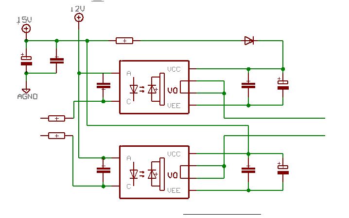
There is a bootstrap circuit that I take the project of a graduate student as a reference and it works. But there are a few things that I don't understand in this circuit.
Like ;
-Why does the PWM signal come from the cathode to the anode?
-Why is a capacitor placed between the cathode and the anode?
-Why 12V is given externally to the anode?
Thank you.
