This thread has been locked.

If you have a related question, please click the "Ask a related question" button in the top right corner. The newly created question will be automatically linked to this question.

BQ24105: +BQ34Z950 Battery Detection Issue

Part Number: BQ24105
Other Parts Discussed in Thread: BQ34Z950

Hello!

We made two pieces (Charger 1, Charger 2) of a dual-channel charger based on BQ 24105. The input voltage of each charger is the same on both channels and is approximately 16 V. (circuit of single channel in application). 

I use 3S Li-ion cells 18650 and BQ34Z950. (). 

We have four identical batteries (№№4,5,6,7).

Quite often, the charging process does not occur properly - when the battery is connected, stat1 constantly blinks (battery detection process).

Before creating this post, I tried to connect each battery to each slot of both chargers. Connected three times with a wait of 5-10 seconds. Designed the results in a table.

At other times, the results may vary slightly. If charging still starts (stat1 is on), it does not always end successfully (at the end, instead of lighting of stat 2, blinking of stat1 starts).

The wires are quite long - about 40 cm per bat + and 40 cm per bat- (from the board with bq34z950 to the board with bq24105). wires 22 AWG.

  • Hi Nikita,

    I think the issue is not battery detection but cycling in and out of charging and charge termination.  If your termination current X (Rtrace+Rconnector+Zbattery) > Vrecharge (75-125mV/cell), then when connecting an almost charged battery, the charger will start to charge raising the battery to the regulation voltage, terminate, battery voltage drops below the recharge threshold and then start charging again, and the cycle repeats.  If you lower your termination current, does the problem go away?

    Regards,

    Jeff

  • Hello! Thank you for reply! 

    I changed R14 with 10kOhm to 23.2 kOhm. Iterm decreased from 100mA to 43mA. as I understand Iterm = Iprecharge. I changed the resistor on the charger 1 slot 1. and did the checks on it. The situation has changed a little in the right direction but not quite :

    1) batt4 blink stat1 (was stat2);

    2) Batt5 first lit up stat1, and when I tried to reinsert  battery stat1 blink, I tried several times - the same problem (before replacing stat1 blink);

    3) batt6 the situation is exactly the same as with batt5;

    4) batt7 is on stat2, tried to reinsert battery -  everything as well (before the replacement, stat2 was also turned on)

    Is this not too small a pre-charge current for a 3500mAh battery?

    Batt5 and batt6 are not as close to a full charge as batt4 and batt7.

    In the datasheet (SLUS606P) in my opinion it’s a mistake - on page 21 it says that the charge current depends on Riset2, and on page 26 that the charge current depends on Riset2. As I understand it correctly on page 26.

  • Hi Nikita,

    Thanks for highlighting the datasheet typo.  I have added to our change lis.

    Since lowering the termination current changed the behavior and it only happens when attaching batteries that are close to full charge, then my speculation about high resistance from BAT pin to battery is likely correct.  Note that the fuel gauge FETs and RSNS are part of this resistance.  If you can reduce any of this resistance, this will also help the issue.  

    Regarding the precharge current, the battery pack manufacturer datasheet may dictate this value.  From an application standpoint, the precharge current size determines how quickly a deeply discharged battery moves from precharge mode to fast charge mode, and therefore battery charge time.

    Since you have a fuel gauge with SMB, can you use the host to determine that the battery is close to full charge when attached and then either disable charge or lower/disable termination?  Even with termination disabled the charge does not provide charge current once the voltage at BAT is at the regulation voltage?

    Regards,

    Jeff

  • Hello, Jeff!

    I repeated the experiment with the slot where I changed the resistor to 23.2 kOhm (for 6 days I did nothing with either the charger or the batteries) - the results changed. Batteries 4,5,7 blinks stat1, battery 6 is charging (stat1 is on; judging by the voltage it is the most discharged battery).
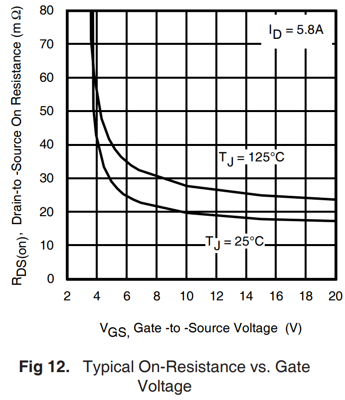
    1. I attach the circuit to the board with BK34Z950. The sensor resistor is 0.01 ohms. FETs irfml8244. Voltage on the gate of the charging fet is 11.8V, voltage on the gate of the discharge fet is 18.5V.. Judging by the graph (screenshot in the attachment), the drain-source resistance is less than 20 mOhm.

    2. Another important detail - we use 18650 batteries (Panasonic NCR18650B) with a protection board (this is a ready-made solution). How much resistance this protection board adds is unknown.
    3. Regarding the pre-charge current: for fast charging, the battery manufacturer recommends 0.5C (1625 mA), we calculated on the fast charging current 1A (~ 0.3C), and the pre-charging current 10% of the fast charging current (0.1A) and I would not want to reduce it.
    4. I also note that if stat 1 is blinking, the LED on the battery does not indicate that the charging process is trying to start. If stat1 is on, the LED on the battery correctly displays the current state of the charge process.
    5. I set the parameters in BQ34Z950 according to SLUA777:

    Charge Termination Taper Current 140

    Discharge Current Threshold 90

    Charge Current Threshold 80

    Quit Current Threshold 20

    Term Voltage 7800
    Are they right?
    6. By connecting via SMB - I will try.
    6.1 What is my sequence of actions?
    6.2 The battery is almost charged. Is this RSOC more than 90%?
    6.3 further, either lower the termination current or completely disable it (TTC low). Right?

    Note: the batteries did not go through the normal charge-discharge cycle, because I do not have another charger, and this is not functioning correctly so far.

  • Hi Nikita,

    If you have oscilloscope, you can take a scope shot of V(BAT), V(OUT) and I(BAT) to confirm that the issue is a V=IR problem as I predicted.  The charger's state machine is very simple and looks at the FB pin voltage, compared to the scaled down battery regulation voltage less the recharge threshold, to determine whether to start charge (square wave at OUT).  The only variable to charge is the termination current or disable termination.     

    I do not support the BQ34Z device.  So, I will move this post to the battery gauge team to answer your other questions.

    Regards,

    Jeff

  • Hi Nikita,

    What are your questions on the bq34z950? Thanks.

    Andy

  • Hi, Jeff!

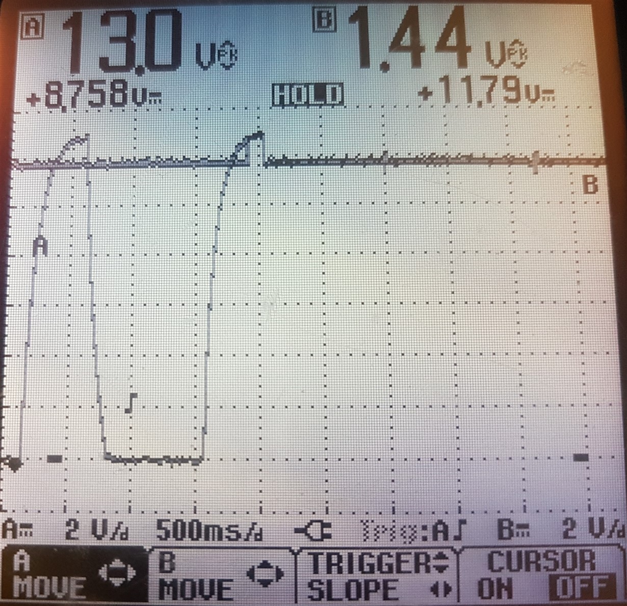
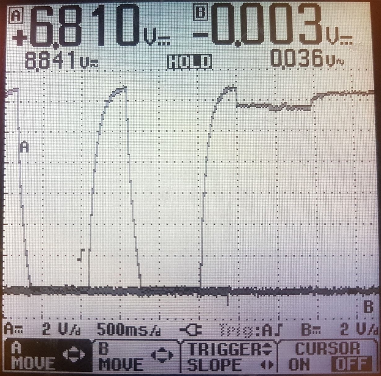
    I tried to take scope shot with an oscilloscope. 

    Channel A - charger, B - battery. After connecting the battery, a straight line with small pokes.

    Channel A - charger out. Channel B not connected. I managed to connect a couple of times this way - the voltage rises a bit, stat 1 lights up, but the battery LEDs do not indicate charging.

    I tried to capture Ibatt, but failed. Connected directly to the battery sense resistor to measure the voltage drop. With an oscilloscope, I simply could not achieve the results that I understood, and when measuring the voltage drop with a multimeter, I got 0V

  • Hello, Andy!

    I set the parameters in BQ34Z950 according to SLUA777 (Iterm of charger = 100mA):

    Charge Termination Taper Current 140

    Discharge Current Threshold 90

    Charge Current Threshold 80

    Quit Current Threshold 20

    Term Voltage 7800
    Are they right? Can incorrectly set parameters disrupt the charger?

    Thank you!

  • See my comments below.

    Charge Termination Taper Current 140

    Discharge Current Threshold 90

    Charge Current Threshold 80

    Quit Current Threshold 20

    [Andy]These settings seem okay, assuming the design capacity of your battery cells are 3500mAh

    Term Voltage 7800

    [Andy] What is the term voltage of the battery cell? 

  • Hi, Andy!

    Design capacity 3350mAh.

    The minimum voltage of one cell is 2.5V. I did 2.6V per cell (like this is the standard minimum voltage for LiIon cell) hence the term voltage is 7800mV

  • Nikita,

    Make sure you set the Charge Termination Taper Current of the gauge slightly higher than the taper current threshold of the charger.

    Also, before you do a learning cycle, the Term Voltage should be set to the minimum voltage of the battery as specified in the manufacturer’s datasheet. If the cell is rated to operate from 3 V to 4.2 V and your application is a 3s application, the term voltage should be set to 3V x 3 cells = 9 V.

    After the learning cycle is completed, this value can be adjusted upwards if there is a need for the gauge to report 0% at a higher voltage.

    Andy

  • Andy, Taper current threshold of the charger is 100mA. Charge temination taper current of the gauge is 140mA. Is it slightly higher?

    I do not remember exactly what value of the minimum voltage was set during the learning cycle, but the learning cycle was successful. As I understand it, this can affect the exact determination of full capacity, but this cannot cause a problem with the charger.

    We are working remotely at home now. I did not take the EVSW distribution from work. Can you send me a BQ EVSW for 34z950?

    Could incorrect calibration procedures lead to such problems? Today the situation is as follows - 2 batteries, where the calibration procedure is carried out correctly, they almost correctly respond to the connection to almost all charging slots (charging, then they indicate that they are fully charged), and 2 batteries on which I am not sure of the calibration are not charged on any of the four charging slots despite the rather low voltage on them (~ 11.5V, and a fully charged battery 12.6V).

    Thanks for the help!

  • Hello, Jeff!

    Do you have any ideas on my problem?

     I tried to reduce the length of the wires and increase their cross section (charger number 1 slots 1 and 2). it did not bring any results. Batteries 4 and 5 currently do not want to be charged on any of the four slots of the chargers, despite the low voltage at the output of the batteries (~ 11.5V, and a fully charged battery 12.6V).

    Thanks for your help!

  • Your taper current setting seems okay. 

    Regarding the BQ EVSW for 34z950, see the following thread.

    https://e2e.ti.com/support/power-management/f/196/p/795374/2942628

  • Thank you, Andy!

    And I would like to get an answer about the charger!

  • Hi Nikita,

    I will move your thread to the BCP team again.

    Andy

  • Nikita,

    As I mentioned previously, this a V=IR issue. If you cannot reduce the R from battery to charger or the Iterm enough to prevent a droop before the recharge threshold, then you will either have to accept the STAT pulsing as the charger enters and exits termination or disable charger controlled termination.

    Regards,

    Jeff

  • Hello,Jeff! Thank you for help!

    The problem really was the increased resistance. Each cell is made replaceable - it is inserted into the slot, where "-" is the household spring battery contact. It itself has a rather large resistance of ~ 150 mOhm.
    I made two experiments:
    1. I soldered each cell directly to our protection board (with BK34Z950)
    2. put a piece of copper foil under each contact of the cell and already soldered these pieces directly onto the protection board (with BK34Z950).
    In both cases, everything began to work well.
    Now ordered the manufacture of springs from Beryllium copper (BeCu). On the results of the community later.