This thread has been locked.

If you have a related question, please click the "Ask a related question" button in the top right corner. The newly created question will be automatically linked to this question.

LM66100: Dual Ideal Diode ORing for Continuous Output Power

Part Number: LM66100
Other Parts Discussed in Thread: TPS2121, TPS2115,

Hi,

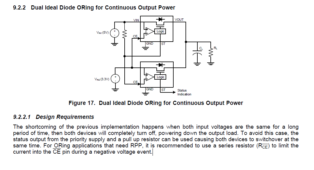
In section 9.2.2, the datasheet describes how to design a circuit such that the output of the ORing circuit remains high during a switchover (make before break).

In my design, both input supplies are LDOs with 3.3V output.

Can I achieve the same behaviour by simply connecting both CE# pins to ground to force both diodes on all the time? 

Thanks,

Michael

  • Micahel,

    You cannot have both LM66100s at the same voltage level for the this configuration. Both LM66100s cannot be on at the same time and they do not support load sharing. 

    The better part for your design is going to be a power mux device such as the TPS2121 or the TPS2115. There is a really good application note that relates to your use case at http://www.ti.com.cn/cn/lit/ug/tidue50/tidue50.pdf

  • Hi Timothy,

    Thanks for your quick response.

    My design is BOM cost limited and I understand your concern.

    Is it safe to implement the design below if both of my inputs are at the same voltage?

    Thanks,

    Michael

  • Michael,

    The referenced solution of ORing together two LM66100s does not support two supplies with the same voltage.

  • Timothy,

    I don't mean to contradict you, but the referenced solution seems to explicitly mention the scenario where both inputs are the same.

    Is there something I'm overseeing?

    Thanks,

    Michael

  • Hello Michael,

    Sorry about the brevity of the previous post. The referenced solution is solving the problem where the priority supply's voltage is dropping ot the point of where it is the same as the auxillary supply. Without the pull-up resistor we are essentially comparing two very similar voltages that can potentially cross each other and switch on and off the internal comparators somewhat rapidly.

    What the pull-up resistor between the primary power supply's ST and input pin does is allow for the ST pin to pull the primary rail low when the switchover event happens. When the LM66100 is disabled the ST pin is pulled low which would then inturn pull down the attached primary voltage rail.

    The reason it is not advisable to force both diodes to be on at the same time in this configuration is that in the on-state resistances can slightly vary from chip to chip. We spec this in the ON-Resistance (RON) section of the datasheet, however the idea is that the voltage potential can vary marginally coming out of either device and lead to some undesirable behaviors with reverse currents.

  • Hi Timothy,

    Thanks for the detailed explanation, I won't be forcing both diodes to be on at the same time. For my application, both input sources will only be on at the same time for a few seconds, and I want to use this circuit to maintain output power during the transition from one source to another. If I use the circuit configured as shown, with the pull-up coming from ST pin, I think it will be OK.

    Looking at the datasheet timing diagrams: If both input supplies are equal, both diodes will want to turn off. Each diode will first drive ST low to signal they are about to turn off (2us delay from actual turn off). This will cancel the "priority" diode from turning off.

    This circuit is really low cost, and is worth testing to see if it can be a fit, I might just test it before incorporating in my design if you think it has a risk of not working.

    Thanks,

    Michael

  • Michael,

    Unfortunately I do not think this is going to work with dual LM66100s. For all intents and purposes being on together at the same time for a few seconds is going to be the same as steady state for the LM66100s and there is a risk with reverse current that you could damage your upstream source. Unlike a regular diode there is no low level reverse current blocking.

    If the power mux soluition is too expensive here you could conceivably get by with two low cost load switches (and a capacitor)- you won't get the efficiency or switchover latency that you would with a proper power mux though. 

  • Hi Timothy,

    The input supplies will be on at the same time for a few second yes, but my understanding is that only one of the diodes will be on because of the ST signal feedback on the enable pin.

    The diodes operate in a make before break operation, so there will be a short time where they are both on but for a very short time.

    Is there a way to simulate this? If not, I'll test it in the lab and see.

    Michael

  • The problem here is that "short time" is a little bit undefined and while it might be unlikely something is going to happen it is still recommended to use a more robust solution like a power mux. I understand though that in cost bound applications this is not realistic though. 

    The lab test would be the best way to go forward with this. There are PSPICE models available on the project page (http://www.ti.com/product/LM66100/toolssoftware), however the lab test will provide the most realistic results.