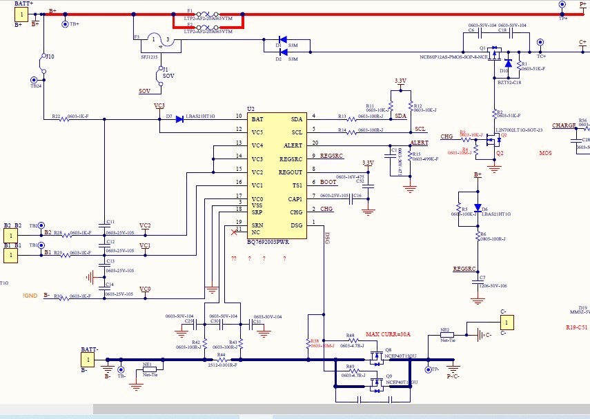
Please help to confirm if the schematic diagram is OK?
This thread has been locked.
If you have a related question, please click the "Ask a related question" button in the top right corner. The newly created question will be automatically linked to this question.
Hi Kevin,
The schematic looks good. A few things to note:
- A power filter capacitor is needed for the BAT pin. The EVM schematic uses a value of 2.2uF for this value, but it the datasheet range is from 1-10uF.
- There is no diode needed on the BAT pin, but it is okay. Figure 12 in the datasheet shows the typical application circuit.
- The components on the cell input filter are large. The 1k resistors will result in a low cell balancing current. I suggest using 100 ohms and 0.22 uF for the cell input filters.
Best regards,
Matt