This thread has been locked.

If you have a related question, please click the "Ask a related question" button in the top right corner. The newly created question will be automatically linked to this question.

TPS61322: TPS613222 draws too much current

Part Number: TPS61322
Other Parts Discussed in Thread: TPS61023

Hi,

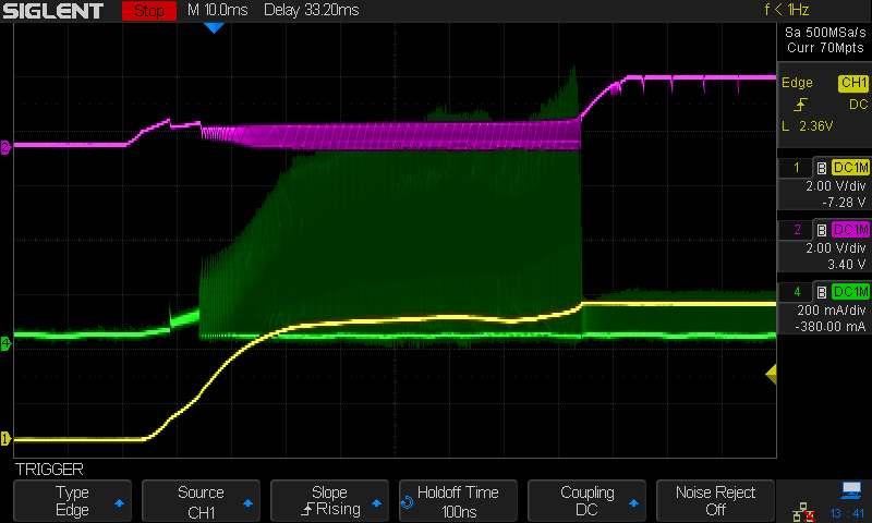
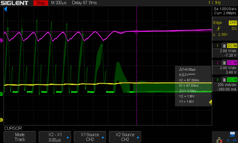
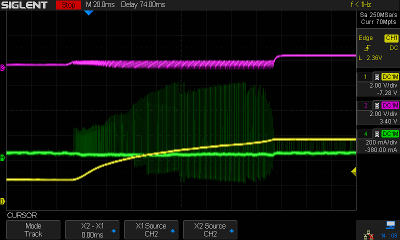
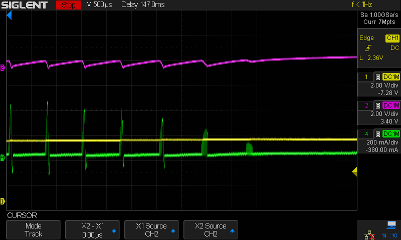
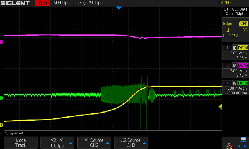
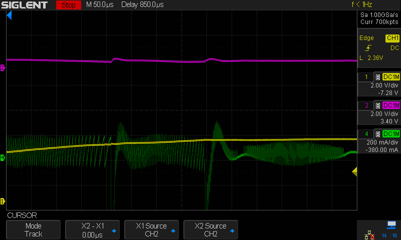
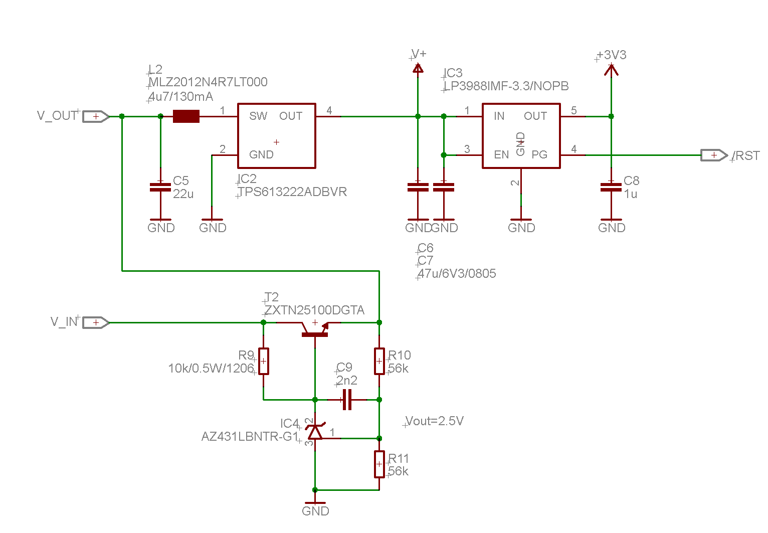
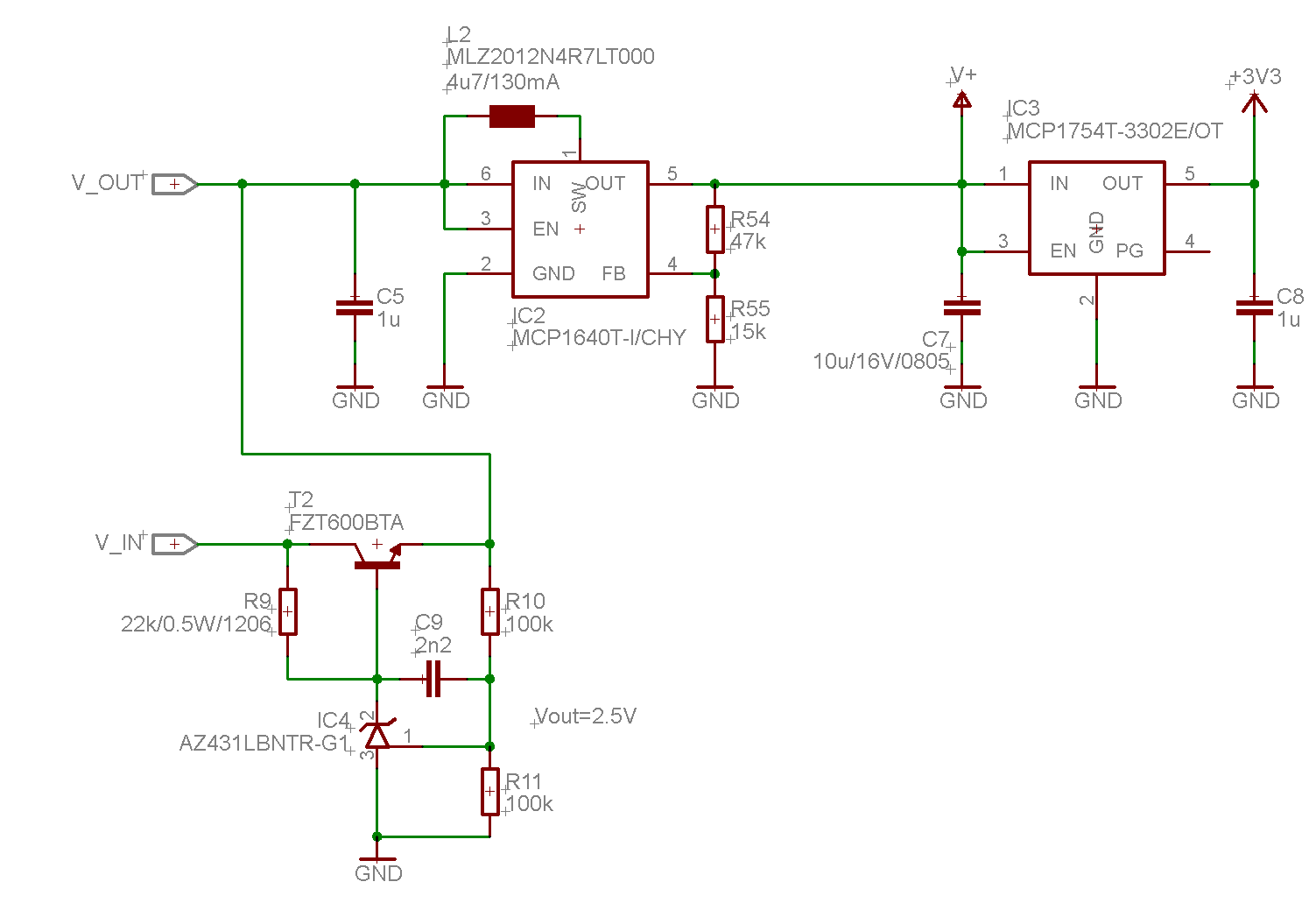
I have been directed to this forum, after having submitted a support request online (case CS0174631). I am having problems with the TPS61322 heating up and drawing excessive current. The converter has a relatively high impedance source that supplies current to it, and I also need to have a large output capacitance (47uF at least). Input capacitance is lower (~ 30uF), used inductor is MLZ2012N4R7LT000. This happens even when I disconnect everything from the output. One question at the beginning, should I share the support ticket info here, or is that accessible for you guys?

Cheers, Frank

  • Hi Frank,

    did the IC damage? does the issue disappear after replacing IC?

  • Hi Jasper,

    yes I did, no improvement. Regarding my other question: can you access the related support case? There is multiple pages of information, including the answer to that. I would copy all this to here, but like to avoid that if possible.

    Cheers, Frank

  • Hi Frank,

    please share the link of the related case. 

    what is the input voltage, output voltage and current in your application.

  • Output voltage is 5.0, input voltage is starting from zero and ramping slowly, output current is zero (no load connected at all).

  • Hi Frank,

    I can't see anything in the link, please help to post your discovery in this post.

    what is the impedance of your power supply? what current do you require during the IC startup?

    if the VIN ramping up very slowly, the device will operate at very low input voltage. the efficiency of the device will be very low before the VOUT reach 1.6V.

  • The impedance is maybe 10 ohms. Yes, efficiency may be low, but the device draws up to 200mA, and there is *no* load connected. Plus, the chip gets noticeably warm in this state.

    I'm copying the info from the support ticket here:

    "I am ramping up the input voltage of the converter, and it draws a quite high current when it is beginning to start up. I first thought that this was due to driving the load, but that happens also when I disconnect it. The TPS chip gets quite warm in this condition, and it struggles ramping the output voltage (stuck at 2.5V, I am using the 5V version). When I raise the input voltage even further, then it overcomes this situation, ramps up to 5V, and works normally." "I just validated the load current at the output of the converter. It is 11mA at 5V, and there is no sign of excessive current draw when I feed that point directly from a bench supply, while slowly ramping up." "Input capacitors all MLCC, combined ~ 30uF. Output capacitance 47uF MLCC (I need that large amount for buffering power loss), inductor is 4.7uH (MLZ2012N4R7LT000, MLCC)"

    "I am quite confident that the problem is more severe. It seems like that the chip switches erroneously when at low input voltage. I have modified the circuit to exclude other possible problems: a) removed the 3.3V post regulator such nothing is drawing load current from the TPS chip. b) replaced inductor with a regular one (2A current, Coilcraft) to make sure that inductor saturation can't be the problem. The problem remains. I have made two scope screenshots (yellow = output voltage, purple = input voltage, green = inductor current). The first picture (1.png) shows the startup behavior, the TPS chip shows some oscillating behavior. I have also checked with my infrared camera - the chip heats up noticeably when I keep it in this state. The second picture (2.png) shows a closeup of the transition to stability. You can see that the inductor current repeatedly peaks up to 1A (again, with no load current at all). When the input voltage reaches 1.1V approximately (cursor), it stabilizes."

    "I made another experiment. TPS chip directly supplied from bench supply via a 47 Ohm resistor. The board still has ~30uF MLCC at the TPS's input, but I wanted to simulate a high impedance voltage source. This also provokes the bad behavior (3.png and 4.png). This can't be only an efficiency problem?"

    "The datasheet states ~ 80% efficiency at VIN=0.9V and Iout = 100uA, which clearly isn't what I am seeing here. When removing the 47 ohm input resistor, the chip behaves better, but still some strange behavior can be seen when the output is approaching regulation (5.png, 6.png)."

    1:


    2:


    3:


    4:


    5:


    6:

    schematics:


  • Hi Frank,

    please go through the startup description in the datasheet page 9. in the waveform 1, the device output voltage ramps to 1.6V very smooth firstly. then the device try to regulate the output voltage to setting value within 2ms. 

    however, as the input power supply is weak and output capacitor is large, the device fails to achieve to reach setting value in 2ms. after that, the device will try to get as much energy from the input as possible to charge the large output capacitor. but the input voltage is weak and drop down, then shutdown the IC. the IC tried again after the input voltage recovers. 

    for such weak power supply, we would suggest increase the input capacitor, reduce the output capacitor and disable the LDO during the boost startup.

  • Hi Jasper,

    I've seen that section, and it is apparent that the chip cycles in powerup, but this doesn't explain why it heats up and draws 200mA during this time. It would be okay to trickle charge the output caps while cycling in and out UVLO, the only problem is the generated losses that my supply can't compensate. It appears to me that the switching action is not 'productive', as if it is circulating excessive current into GND and/or discharging the output cap into GND. Regarding the LDO: I repeat, there is *nothing* connected to the output of the TPS chip, except for the output cap. I have tried reducing them from 2x47uF to 1x47uF, this doesn't solve the problem. Increasing input capacitance is prohibititve because of space constraints.

  • Hi Frank,

    let me try to reproduce the behavior with EVM and figure out the root cause.

  • Hi Frank,

    did you try to change the inductor to a higher saturation current device? the inductor in your schematic has only 300mA~400mA saturation current.

    if not, could you try higher current inductor. just make sure the issue is not caused by the inductor.

  • Hi Jasper,

    thanks for looking into this! It should already be enough to turn down current limit on the (linear) bench PSU.

    The later measurements were all taken with a larger 4.7u inductor (from my Coilcraft sample kit, saturation at  2A+).

    Cheers, Frank

  • Hi Frank,

    we reproduce similar behavior in the EVM. and still prepare slides to explain every detail.

    to be simple, the root cause is that the VIN is quite low which causes very low efficiency. as the output capacitor is large, the device need long time to charge the COUT. the power loss in the IC causes the high temperature in the IC.

    if you need large output capacitor in the application and the power supply is weak. I have to suggest other device. may i know what is the output capacitor in your application?

  • Hi Jasper,

    thanks for investigating! To my suspicion, the TPS chip must do something wrong internally. The correct approach would be to repeat its soft start after having gone UVLO, which it apparently doesn't. It also appears that large currents circulate repeatedly on the input side (watch the sinusoids in the pictures - the TPS chip must be shunting the inductor to GND during this time), which don't contribute to charging the output.

    I am attaching an updated schematic, that solution works but requires two additional resistors which I don't have space for. There is an additional ~30uF MLCC at V_OUT which is on another page (but physically close). I could reduce the output cap to 10uF. The V_IN signal is a rectified and buffered voltage from a variable-frequency AC source (2Vp to 100Vp), which is why I need capacitance to 'survive' the valleys. If you ask, no, the TPS613222 still shows the bad behavior with the reduced 10uF at its output. If you can suggest a replacement of the current regulator chip at a similar price point but with smaller footprint, then I'd be glad!

    Cheers and Happy Easter

    Frank

  • Hi Frank,

    thanks for pointing it out. I will check if there is soft-start after the circuit repeat.

    what is output current of the LDO for 3.3V?  What is the current out of the FZT600BTA when you do you experiment? 

  • Hi Jasper,

    there is ~20mA current draw from V+, and another ~30mA from +3V3.

    In my experiment, I used a bench supply to feed the FZT600BTA, and I had cut the PCB track between V+ and everything else in the circuit to ensure that there is absolutely no current draw. I could then observe up to 200mA of current drawn from the bench supply. It was possible to keep the TPS chip in this oscillation condition, without it ever being able to fully charge V+. It was getting relatively hot in this state, approx 40degC.

    Cheers, Frank

  • Hi Frank,

    from the waveform you share, the inductor current actual ramp up from zero to 200mA or 400mA. that is the soft start function of the device. the soft start is controlled by internal reference voltage ramping up in 2ms. as this period is short, it doesn't help much to limit the current.

    is it possible to change the NPN to MOSFET? so the current from V_IN wouldn't be limited by the R9. 

  • Hi Jasper,

    I can't confirm 200~400mA of current draw. Please have a look at picture '2', there you can see inductor current spikes of up to 1000mA (green), which surprisingly doesn't seem to contribute to output capacitor charging. At this high current level, a 47uF capacitor would be full at 5V within 230 microseconds, but the output (yellow) only rises marginally. That's where my suspicion comes from, that the regulator is erroneously circulating current when in this condition.

    The NPN is a darlington with hfe of 20,000 typical. The bottleneck is the source of the entire circuit, which is an AC generator with an output impedance in the order of 5 to 20 ohms.

    Cheers, Frank

  • Hi Frank,

    the peak current of the device is controlled by internal COMP signal. the COMP could ramp to very high because the VOUT is lower than setting value after soft-start.  the low side MOSFET will be always on if the peak current is lower than the COMP signal and the current limit as this device don't have maximum on time limitation.

    one possible solution for your application is TPS61023. this device will start up at 1.6V and UVLO at 0.5V after start-up. this feature should help on such weak input application.

  • Hi Jasper,

    I agree, that does explain what I am seeing. Thanks for recommending the TPS61023. Sadly that chip is overrated for my application (max 50mA current draw) and above my BOM price point. Thanks anyway for looking into this, at least now I can be sure that there is no easy trick to make the TPS613222 work in my application.

    Stay safe,

    Frank