This thread has been locked.

If you have a related question, please click the "Ask a related question" button in the top right corner. The newly created question will be automatically linked to this question.

TPS54316 sawtooth output at >4,5V Input

Other Parts Discussed in Thread: TPS54316, SWITCHERPRO

Hello,

I'm working on a battery powered Project. My conditions are

  • DCDC output 3,3V, 3A.
  • DCDC input 4,8V-6V (4AA in series, Akku/Battery)

My schematic is the following.
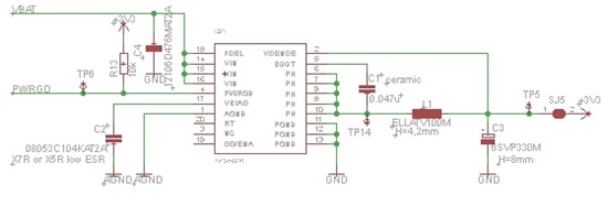
  • Input cap (C4): 12106D476MAT2A
  • Inductivity (L1): ELLATV100M
  • Output cap (C3): 6SVP330M

If I connect VBAT to a regulated voltage supply and try to determine the operating voltage area I get three areas.

  • 0V-2,9V: nothing happens
  • 2,9V-4,3V: up to 3,3V the output follows the Input, output  then stays at 3,3V
  • >4,3V: output  is sawtooth

Where the 0V-2,9V and 2,9V-4,3V range seems to be ok, I do not understand what is happening above 4,3V

Unfortunatelly this is the Interesting voltage range for me.


Krind Regards

Michael


  • That output capacitor and inductor may produce a dsign on the edge of stablity.  I would have to see waveforms to be certain (include both PH and Vout).  You can look at SLVA105 to get an idea of what component values to use.  The TPS54316 uses internal compensation.  It relies on the output inductance, output capacitance and output cap ESR to stabilize the loop.  I would recommend using compomnets that place well inside the shaded areas for optimum stability.

    Using switcherpro shows this design to be stable.  I will need to see waveforms to verify.  Also, can you measure the loop response?  That will tell you all you need to know.  I would measure at Vin = 4 V.

  • Hello John,

    unfotunately I only have a analog oszi and a really slow function generator. Is there a chance to measure the loop response without opening the loop and "destroying" the layout?

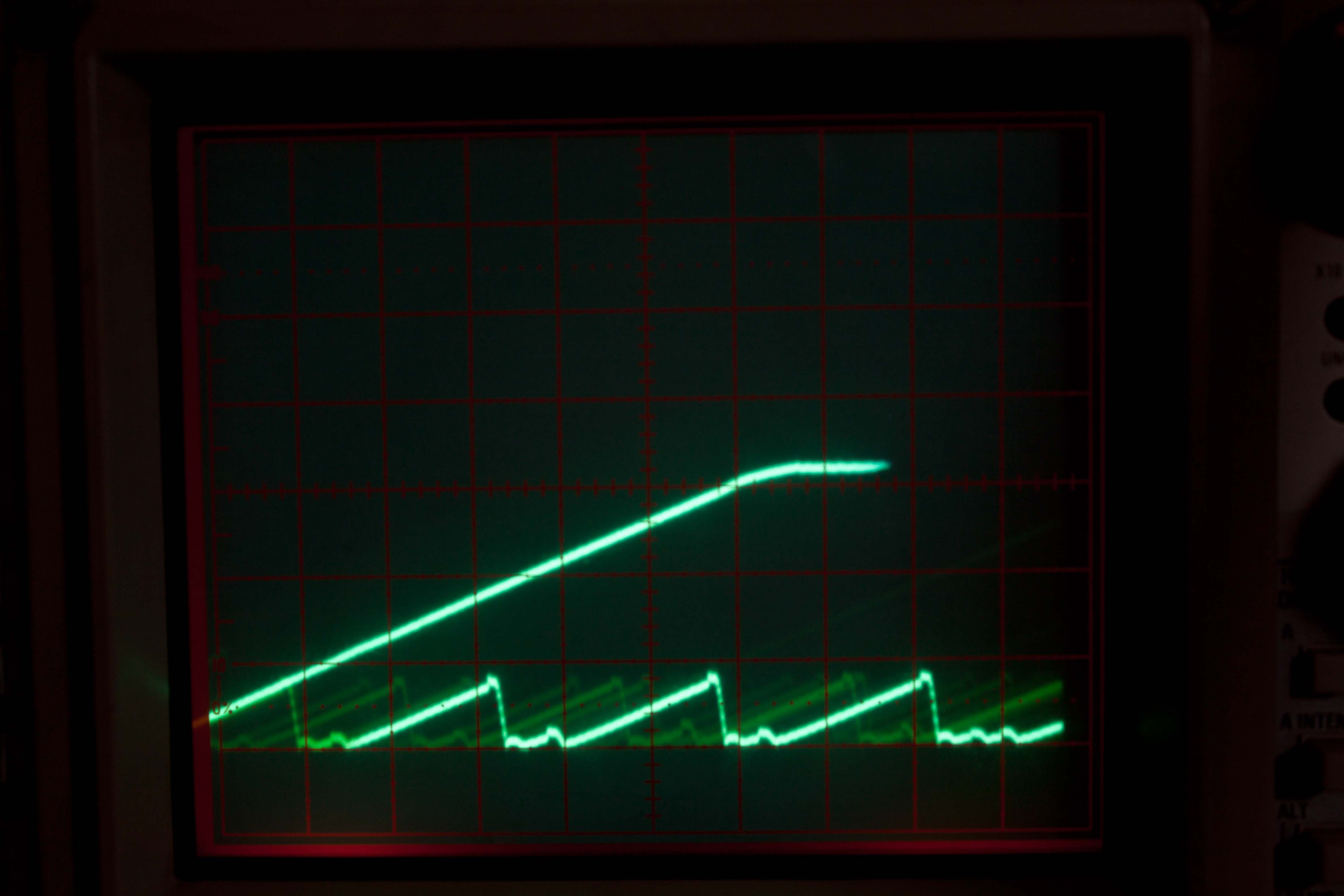
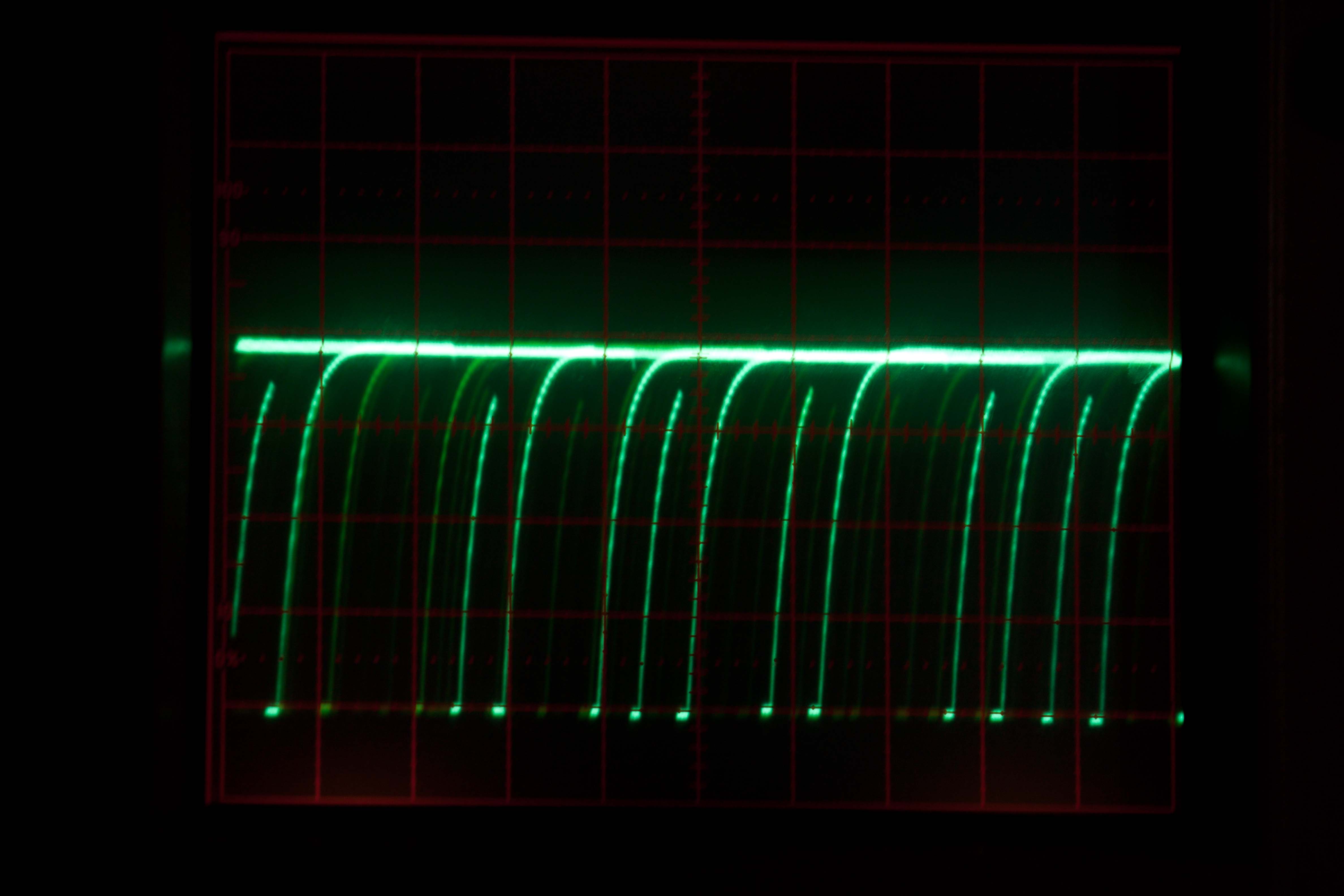
    I tried to make a picture of what is happening at the output by camera.

    I'm taking a picture of PH tomorrow. But the signal looks like a PWM signal (short on, long off time) after the output shows the sawtooth.

    I'm sorry for that poor quality.

    1V, 100us


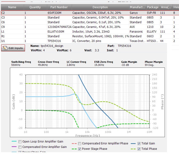
  • Here are my SwitcherPro outputs:


    Edit: After posting this post I recognized the low phase reserve at the power stage and the dip of its gain at 2kHz. Is it possible that this one is causing my problem?

  • I already checked switcherpro and got similar results.  Regarding your waveforms, is the top trace Vin and the bottom Vout? are you triggering right at start up?  Can you also show SS/ENA?

  • Hello John,

    >Regarding your waveforms, is the top trace Vin and the bottom Vout?

    Both waveforms are Vout at constant Vin at about 4.5V. 

    Is the power stage gain and its phase reserve in SiwcherPro ok?

    I also tried a output cap with 120mohm esr in SwicherPro and the phase reserve increased. Unfortunately I had to choose the 25mohm one because the distributor has no other cap in stock.

    >are you triggering right at start up

    No this is a continuous sawtooth signal.


    >Can you also show SS/ENA?

    SS/ENA is not connected.


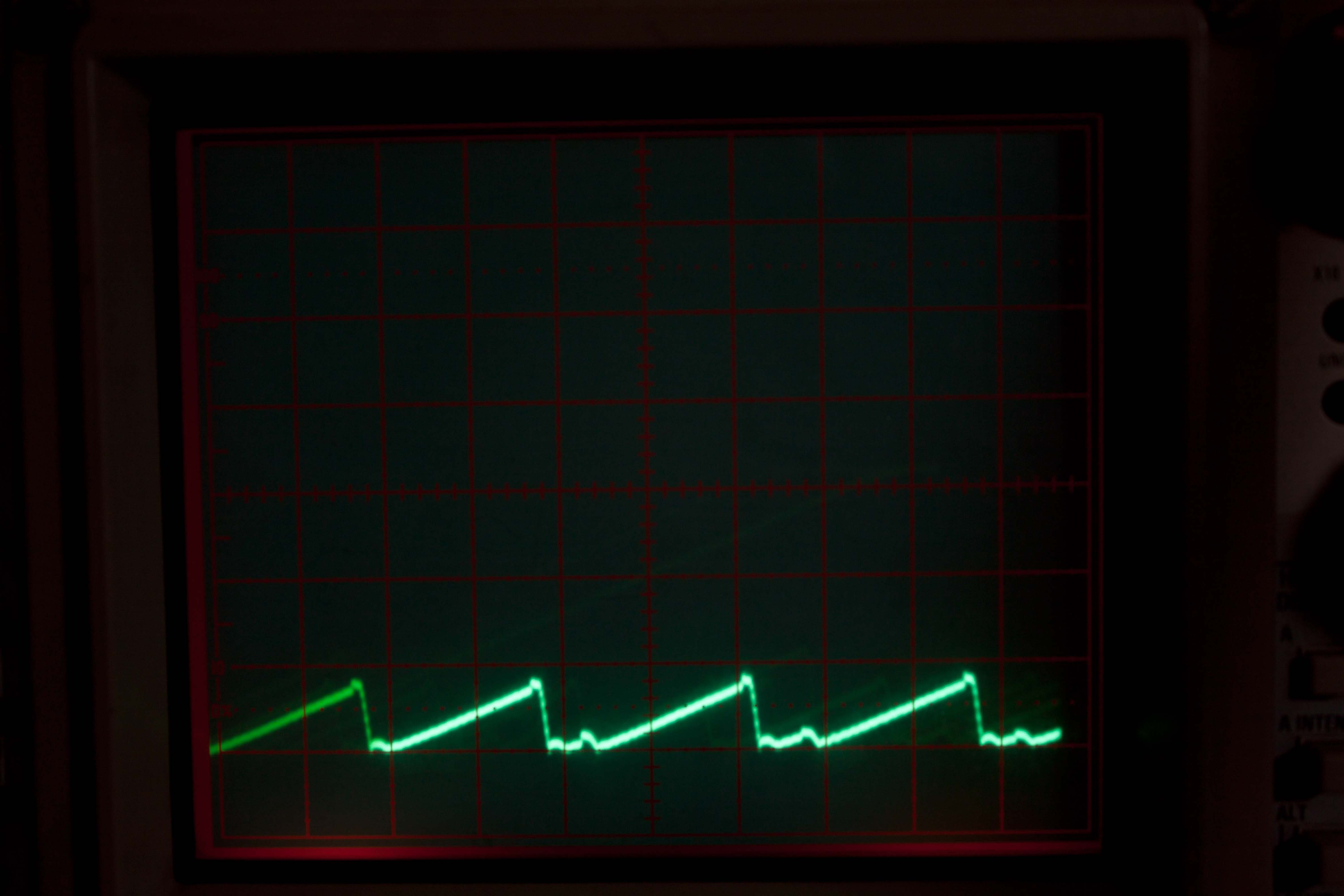
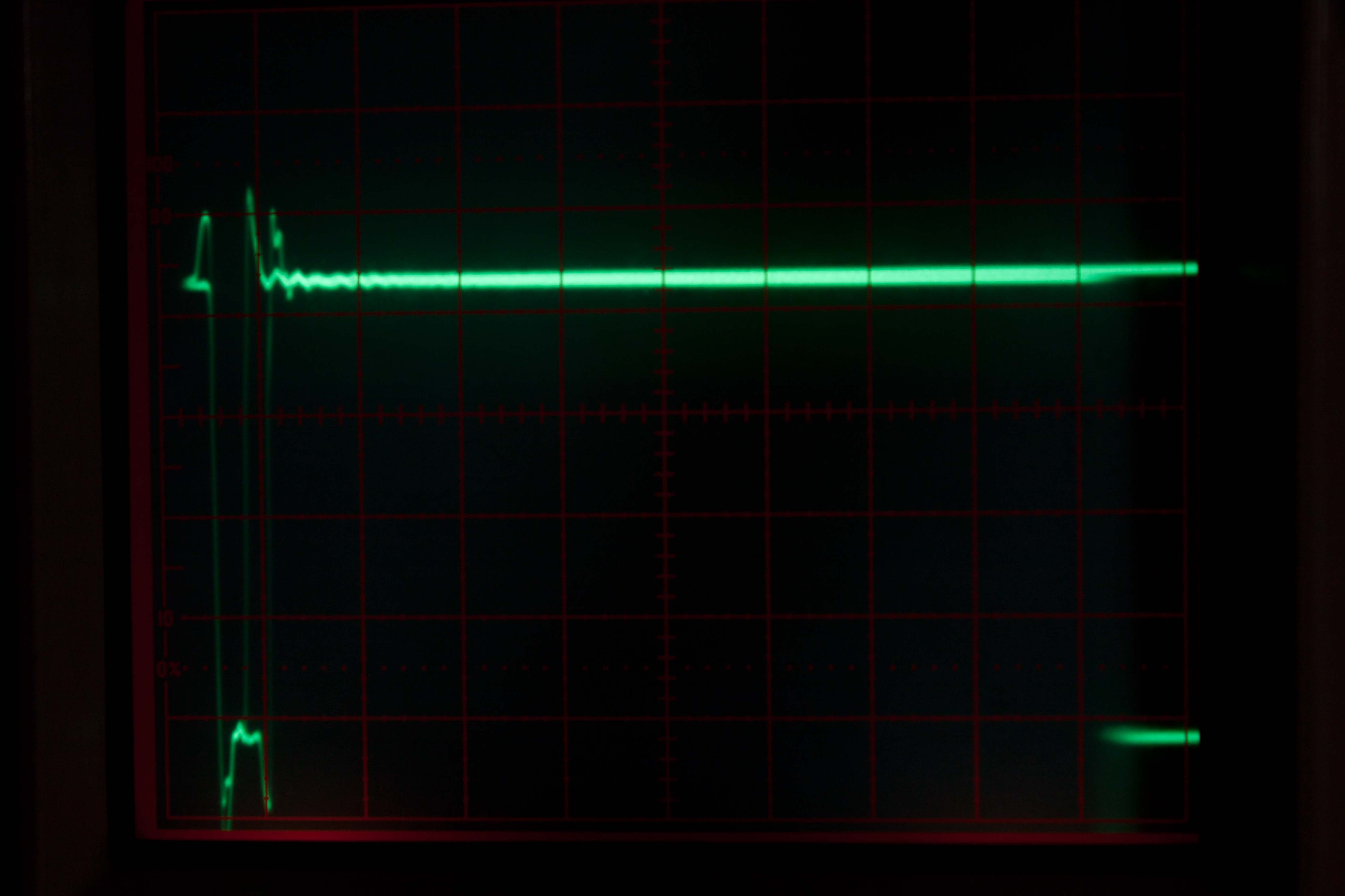
    I took two more pictures:

    These are also continuousat about 4.5V. SS/ENA repeats the same way as shown in the picture. Short off then long on phase.

    SS/ENA, 1V, 0.2us

    PH, 1V, 0.5ms


  • It is really hard to tell from those scope traces.  It looks like SS/ENA is continuously resetting.  How Much undershoot is there on PH?  Do you have any idea what your load condition is?  Will it start up normally into a no load condition?


    You may need to contact your local AFA to take a look at this.

  • >How Much undershoot is there on PH?

    It is about 1.1V under 0V.


    >Do you have any idea what your load condition is

    Two 10ohms in parallel.


    >Will it start up normally into a no load condition?

    No same effect there. This was the reason I tried with load.


    Can you please tell me what an AFA is?!

  • Today I've changed the output cap to 595D477X0010R2T, which leads to better phase reserve at SwicherPro, but there seems to be the same problem.

    Please give me a hint what to check next.


  • You could try something like Sanyo OSCON 4SVP680M.  Something with 25 mohm ESR and 680 to 2200 uF capacitance.  That should be ell into the best area for stability.  If that doesn't work then we need to look elsewhere.  What is your layout like?  Is everything properly grounded?  The input capcitor placement is critical.  The ceramic input bypass cap needs to be right on the VIN and PGND pins.  You can't get too close.  Let me know if any of this works.

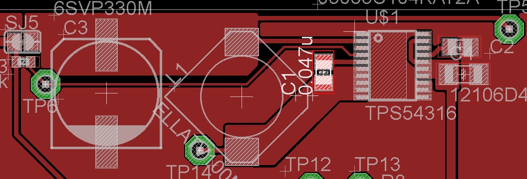
  • I took a snapshot of the layout. I tried to place all components as close as possible to the chip.

    The output cap Ive tried before had 25mOhm.

    The Power Pad is not connected because of hand soldering. The area under the chip is properly connected to GND.

    Description right to left:

    Input cap, bias cap, chip, boot cap, inductor, output cap.

  • You can try attaching C4 directly accross the VIN and PGND pins.  It should probably b at least 10 uF.


  • John, you saved my day.

    This was the reason. I removed the right pad and moved it directly to the PGDN pins and now the output is stable from 3,3V to 6V.

    Thank you for spending time for my beginner questions.


    Michael Sonst


  • You're welome.


    To close, always make sure the input decoupling capacitor is as close as possible to the VIN and PGND pins.