This thread has been locked.

If you have a related question, please click the "Ask a related question" button in the top right corner. The newly created question will be automatically linked to this question.

UCC256302: Incorrect duty cycle in gate signal

Part Number: UCC256302
Other Parts Discussed in Thread: UCC256402, , UCC25630-1EVM-291, UCC256404, UCC256304, UCC25640EVM-020

Hi.

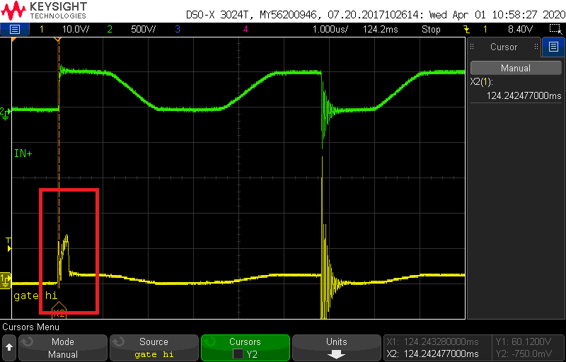
Gate signal falls apart immidiately after it reaches 12 V and stays down until the next cycle comes. Slew rate is in range. Boot cap and Vcc are stable. This happens in both continuous control range and burst mode. 

Thanks,

Ehsan

  • P.S. the green line is the voltage in middle point i.e. HS.

  • Ehsan

    First off I we recommend that you use UCC256402 instead of UCC256302.  UCC256402 is a pin-to-pin compatible improved version of this device.  Details are in this app note http://www.ti.com/lit/an/slua966a/slua966a.pdf

    It appears that the gate drive is only high for about 250ns, which is the minimum gate on time.  We need more information on your design in order to help here.  Can you please provide the following information?

    • Schematic
    • Design specification (input voltage range, output voltage, output power)
    • Operating conditions (input voltage, output voltage, output power) of design at moment of interest

    In the meantime, if you have not already, we recommend you use our excel design calculator for UCC256302 http://www.ti.com/lit/zip/sluc634 (UCC256402 excel calculator http://www.ti.com/lit/zip/sluc675) to verify that there are no errors in your design.  We also recommend that you use our SIMPLIS model http://www.ti.com/lit/zip/slum596 (UCC256402 SIMPLIS model http://www.ti.com/lit/zip/slum684) to verify your design in simulation if you are having trouble getting the hardware to work.

    Best Regards,

    Eric

  • Hi Eric,

    Thanks for your fast response. I have already checked the Excel tool in design phase of the project.

    - The schematic is unfortunately confidential and cannot be published. I can give you all the info you need though.

    - Input range is 505 - 600 V and the output is regulated on 15 V and 50 W.

    - Operating condition is 550 V and 5 W. Switching frequency seems to be set at about 95 kHz.

    (- Capacitors on VCR Pin are C_upper = 470 pF and C_lower = 1.5 nF. )

    Could it be, that the adaptive dead time is too high?

    I would appreciate it, if you'd highlight some of the reasons, which come to your mind.

    P.S. Are the 256302 and 256402 easily interchangable or should the schematic and design be changed?

    Thanks in advance.

    -Ehsan

  • Ehsan

    UCC256302 and UCC256402 are designed to be easily interchangeable, you only need to change component values.  No PCB layout changes are needed.  Section 7.4 "Using UCC256404 on UCC25630-1EVM-291" of this app note http://www.ti.com/lit/an/slua966a/slua966a.pdf explains what changes were made to enable UCC256404 to work on a design originally for UCC256304.  These changes also apply for UCC256402/302.  Earlier sections in this app note go into detail on the differences between the two parts and what calculations are different.

    If I understand correctly, this issue is occurring at light load. One potential issue that may be occurring here is that the slew rate on the switch node can reduce too far where UCC256302 can no longer detect it.  The minimum slew rate that UCC256302 can detect is 1.0V/ns.  If this is causing the issue, switching over to UCC256402 will solve your problem since it has a minimum detectable slew rate of 0.1V/ns, which is 10x smaller.

    For the VCR capacitor and other component values, I recommend that you use our excel calculator to verify that the component values are correct

    Best Regards,

    Eric

  • Hi Eric,

    The slew rate falls perfectly within the specified range and modifying it didn't help much. Although, I reduced the lower resistor in the feedback voltage-divider and the problem is solved! Do you have an idea why? There doesn't seem to be a connection between the two! BTW, the problem was in all loading conditions there and not only in light loads.

    Thanks,

    Ehsan

  • Ehsan

    I'm not sure which "feedback resistor" you are referring to.  Is it the same as R19, R23 in UCC25640EVM-020?

    If this resistor divider network is different than what you expect, the LLC converter can be operating at a point that is different than originally designed.  Operating at this higher voltage point could have caused several different things that could have caused the misbehavior you were seeing, from a fault condition being triggered or the power stage unable to have sufficient gain to work at the value the actual resistor divider network was set at.

    Best Regards,

    Eric

  • Hi Eric,

    Yes these are the resistors. I adjusted them very slightly though.

    Regards,

    Ehsan

  • Ehsan

    I'm glad to hear that the problem has been resolved.  If you have any further questions please let us know.

    Best Regards,

    Eric