This thread has been locked.

If you have a related question, please click the "Ask a related question" button in the top right corner. The newly created question will be automatically linked to this question.

TPS40210: Unstable power supply found on several boards

Part Number: TPS40210

Hi,

At our company we have an ultrasound design with TPS40210 power supply (for the ultrasound transducer). Input is 6...8.4V (2x Li-ion batteries), output is +/-85V. Schematic is attached below:

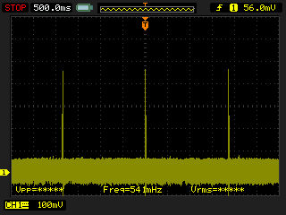
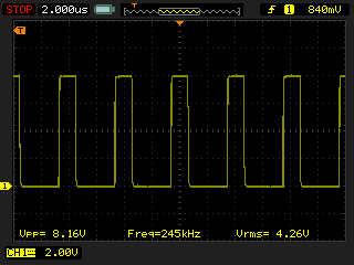
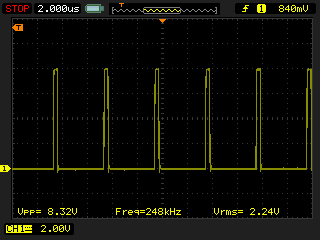
Switching frequency is set to approx. 230kHz. 82kOhm resistors are the basic load of the circuit. 'Real load' comes only when pulsing is switched on but it is just several mA, not so much (because overall duty cycle of the pulsing is very low).

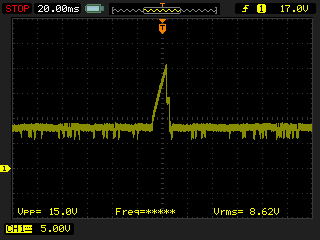
We made two batches of the board, totally 12pcs (2x 6pcs). We found 1-1 boards in both batches with unworking supply. They just cannot switch on even without the pulsing load. Output is trying to set up but cannot so it is unexpectedly swinging between several V and several 10V.

SS pin was checked and found the overcurrent condition specified in the datasheet (switching on/off in every 2s). I tried to decrease R48 down to around 55mOhm (2x 0.15 Ohm added parallel) but no change was found. I changed coil to 220uH but he same result was found. I tryed to decrease the output voltage to half of the current but did not help.

I am sure this is not a technology issue (our assembly house always makes quite good work) but a design issue. Any idea, what to change or recalculate?

Best regards,

Istvan

  • Hi Istvan,

    Sorry to hear that you are having trouble. 

    From a first glance, it appears that you have designed the boost converter correctly.

    Can you give scope shots (a few cycles) of the COMP, SW, and SS, and DIS pin? 

    Thanks,

    Richard

  • Dear Richard,

    Thank you for your fast response. I am measuring the following results and plots:

    SS is continuously restarting:

    Like overcurrent condition specified in the datasheet. But only two of the boards are showing this out of 12, and output current is very low, even when it is loaded. The one what I am testing shows this plot with the 0.22 Ohm current sense resistor reduced to about 0.055 Ohm.

    RC pin looks to be fine, around 240kHz switching frequency, as planned originally:

    ISNS (Current Sense) pin shows some interesting behavior, peaks at about two seconds, like overcurrent, although there is not much output current (and capacitance).

    Looking it a bit closer:

    Power MOSFET Gate has a similar power up/down pattern. It is starting in every ~2s with somewhat different duty cycle:

    On HV_POS output of the regulator seems to be a bit crazy with some unexpected peaks:

    Any idea what to change to resolve the issue?

    Istvan

  • Hi Istvan,

    Sorry for the delay.

    Is it possible for you to DNP C54 to see if the initial positive rail is working? Do your other boards regulate correctly?

    My understanding so far is based on that if your other boards are able to start-up and can regulate properly, it may be an issue intrinsic to this board, even if the assembler does quite good work. 

    Design wise, your schematic looks quite similiar to this one: http://www.ti.com/tool/PMP10091, so I would suspect the schematic to be okay. 

    Thanks,

    Richard

  • Hi Richard,

    Sure, I will test it when I visit the lab next time (we are on home office at the moment and I visit the lab only once a week or so). Probably on Friday. I will give you a feedback.

    Originally I had 2 boards with this issue. On one board I replaced the controller and it started to work well. Now I have a second board so I have to investigate (once never-twice always, you know).

    Other 12 boards are regulating correctly.

    I know this schematic, I used it as one of the base of my schematic.

    BTW, what about the component values? Are they correct? Can a miscalculation cause a similar issue, or is it impossible?

    It is not fully clear to me how to calculate the feedback compensation network values. A small program for this calculation would help a lot at this point but could not find any on TI website.

    Regards,

    Istvan

  • Hi Istevan,

    The component values look correct to me, and if a miscalculation caused a similar issue, this would have shown up across all the boards.

    As for the compensation values, you can generally follow the method described in the datasheet, but will need to tweak the values when running the board.

    Thanks,

    Richard