


We set the voltage of the power supply to 600 mV and the current to 1 mA size.
The set value was measured by putting it on the board. The pin settings on the board prior to insertion have no load connected to /EN = GND, VOUT_EN = VSTOR, or VBAT.
The actual measurements then obtained were VBAT = 508 mV, VSTOR = 15.6 mV and VOUT = 13.6 mV.
In the next experiment, the measurement was made by connecting a 2V charged capacitor to the VBAT so that it could bypass COLD START mode.
VBAT = Slowly decreased at 2V, VSTOR = 16mV and VOUT = 16.4mV. I don't know why the measurement comes out so low.
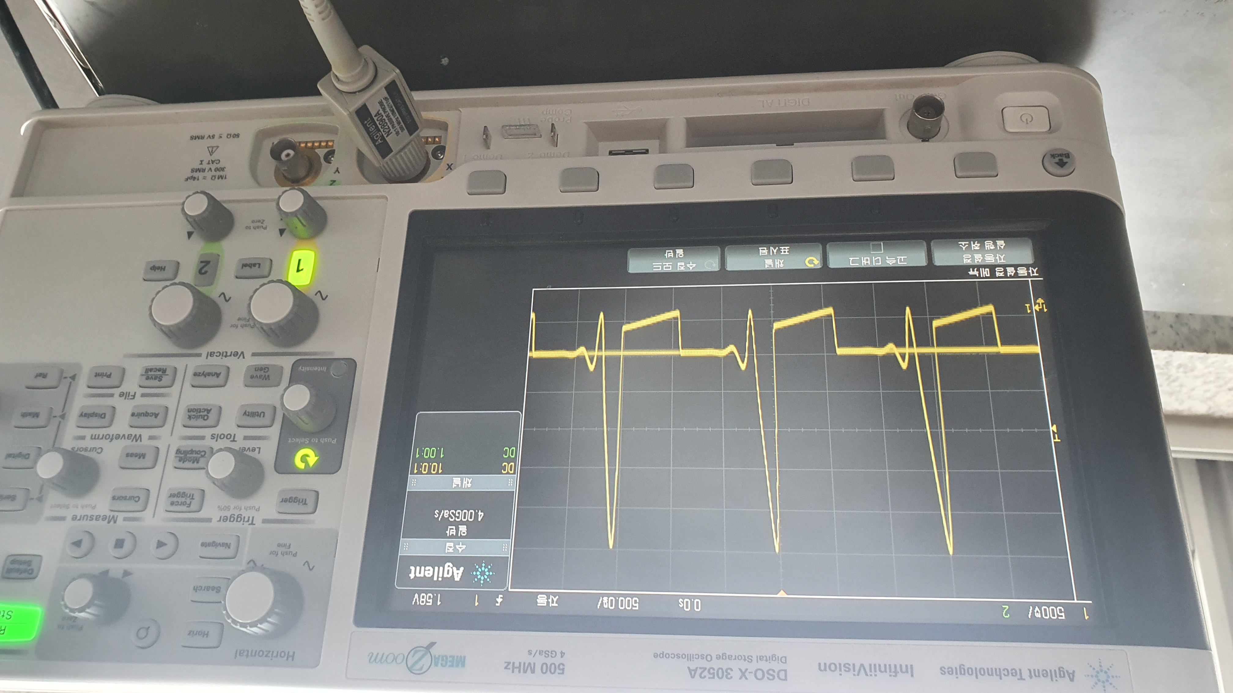
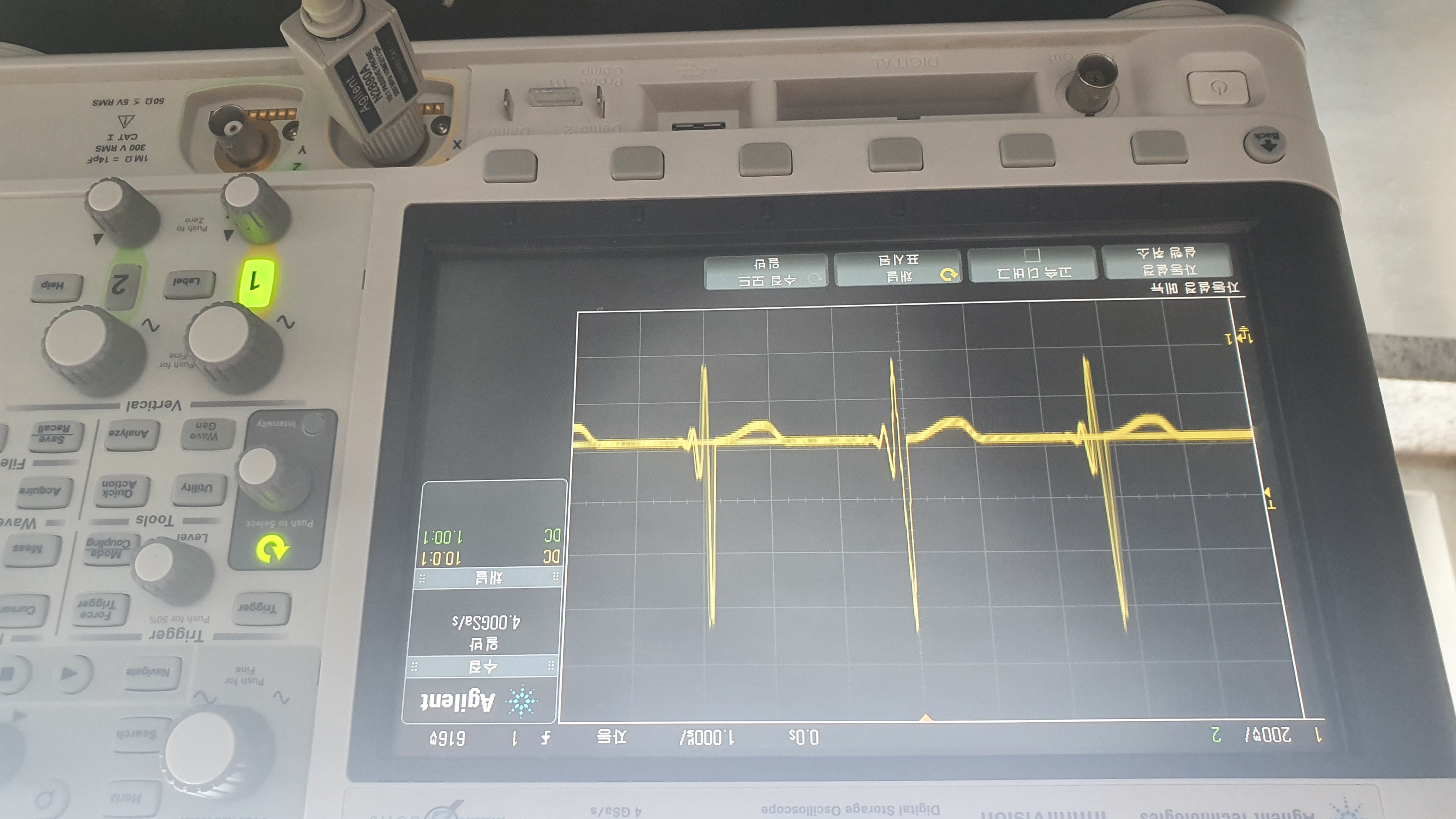
So I made a measurement with an oscilloscope to check if the LBOOST pin is switched, and I want to confirm whether the picture above is measured correctly.
If the LBOOST pin doesn't work, I want to know how to go through the next step and proceed correctly.