This thread has been locked.

If you have a related question, please click the "Ask a related question" button in the top right corner. The newly created question will be automatically linked to this question.

TPS782: TPS782 with DC/DC converter for MCU supply

Part Number: TPS782
Other Parts Discussed in Thread: TPS7A02, TPS63806EVM, TPS63806

Hi Team,

Need your inputs on this. Our customer is using an MCU to control a battery charger. On the field, as the the MCU goes standby mode it would need to consume 3.3V at very low currents all the time. This would make the current DC/DC converter (MCU supply) to consume more than the sleeping MCU.

The TPS782 would perform much better when the controller is in deep or light sleep and when most of the system is powered down. This would enable the controller to wake up when needed and then activate the converter to come online before loading up with more current.

Do we have any suggestions, app notes or design documents to manage this handover between the LDO and switching converter? Thanks in advance!


Kind Regards,

Jejomar

  • Hi Jejomar,

    This is a very good way to minimize standby power. One trick to make sure that the LDO's Maximum VOUT is less than the DC/DC converters minimum VOUT. This ensures that when the DC/DC converter is enabled, it will be supplying 100% of the load current. 

    Here is a reference design discussing how to use a DC/DC in parallel with an LDO: http://www.ti.com/tool/TIDA-00393?keyMatch=LDO%20DC/DC%20STANDBY&tisearch=Search-EN-everything

    Also, we now have the TPS7A02 which is even lower IQ than the TPS782!

    I hope this answers your question.

  • Thanks for that. tiduaa4 document answers that.
    Yes I saw the TPS7A02 also. Seems to have higher dropout - though not easily compared at the same voltage and currents (e.g. 3.3V, 150mA)

    regards,

    Brad

  • John & friends,
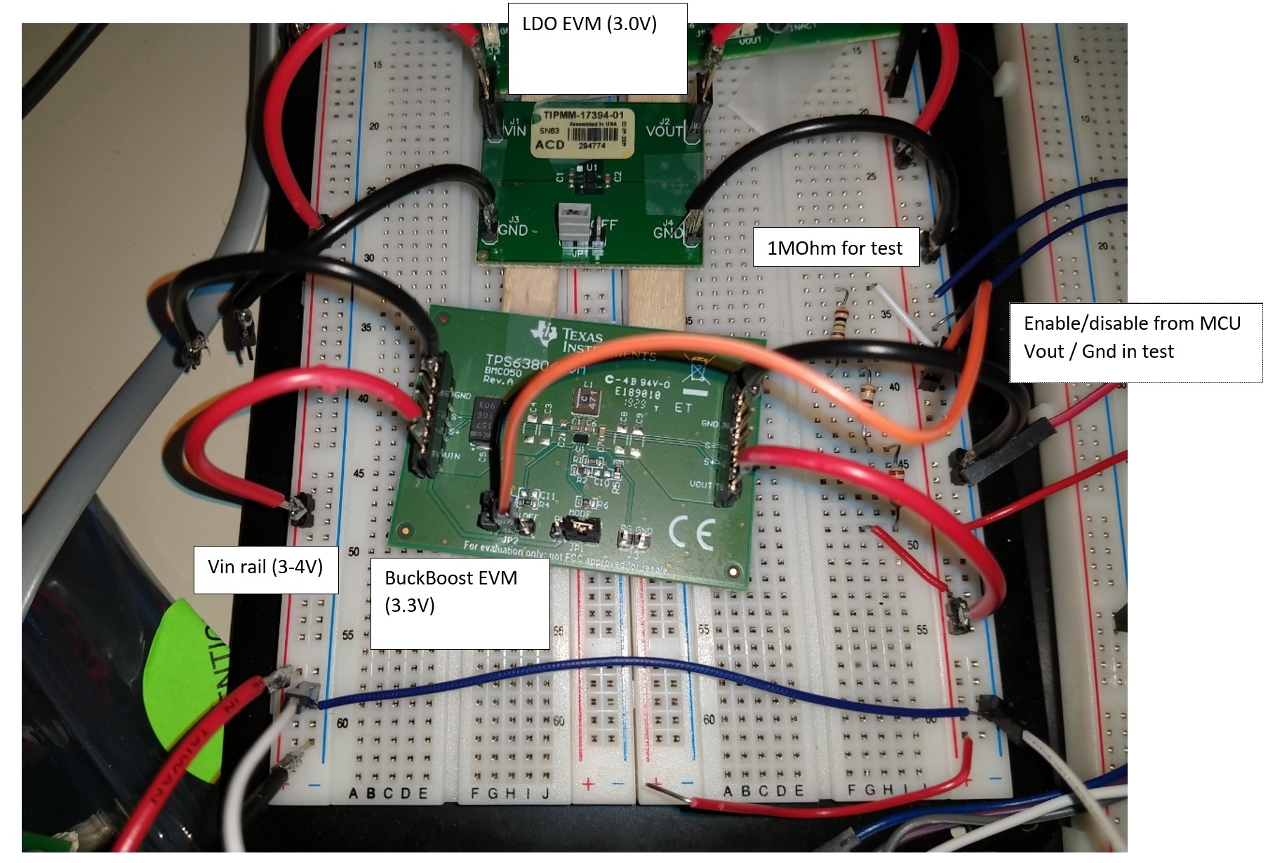
    I've hooked up a TPS782EVM and a TPS63806EVM in parallel as per the reference design. The DC-DC is regulating at 3.3V, the LDO well below at 3.0V
    I'm trying to understand a couple behaviours:

    1) when the dc-dc takes over from the LDO supplying ~100mA, the LDO to ground current increases from ~4.3uA to ~12.7uA. I measured the Iout at the LDO (wanting 0A) and got ~ -0.8mA

    2) when the LDO is on at low load and the DC-DC disabled by jumper on the EVM, the DC-DC ground sinks 35uA. DC-DC Iout - 35uA.

    thanks for any help

  • HI Jejomar,

    For question #1.

    A.)To ensure the DC/DC is dominating, make sure that the tolerances as such that the minimum regulation voltage of the DC/DC is higher than the maximum no-load voltage of the LDO. Connecting the two EVM's in parallel is not an ideal layout and maybe there is a larger drop across the wires.

    B.) Most LDO's do increase IQ when in drop-out. The TPS7A02 is better at managing this.

    For Question #2. This is likely an artifact of the DC/DC converter. The only obvious leakage path I see could be the feedback resistance of the DC/DC but what you are seeing seems larger than that. Please contact someone on the DC/DC team to see what is going on here. 

    I hope this helps.

  • Thanks. I don't understand this answer
    A) I measure the LDO regulation voltage as 3V and the DCDC regulation voltage as 3.3V (at the end of wiring / common rail). Is this larger difference an issue for the LDO?
    B) I'm well above dropout. The above numbers were the same at two different input voltages i tested

    #2 how do I get a DCDC team member to advise?

    ta

  • Hi Jejomar,

    For A). Sorry if I was not clear. With the LDO regulation at 3V and if its VOUT is above this target, while the pass element is off or open, the LDO Error amp is running full speed trying to monitor and regulate the output. This mode of operation is very similar to when it is actually in drop-out and wants to be sure a sudden increase in VIN does not pass through to VOUT

    For B). I have notified our DC/DC team and hopefully, they can provide some insight.

    I hope this helps.

  • Hi Brad,

    When the TPS63806 is disabled via EN pin, its output is floating and there is only a small leakage current which should be well below 1 μA. The majority of the leakage current should go through the voltage feedback divider. Have you maybe modified the voltage feedback divider on your TPS63806EVM?

    Best regards,
    Milos

  • Thanks Milo.

    no modification. both LDO and 63806 EVMs are as from the factory. only connected Vin,Vout,Gnd and enable for the dc-dc.

    I appreciate any further support

  • Hi Brad,

    Could you please test the TPS63806 EVM separately from the LDO EVM? Connect a DC source to the input, disable the device (EN=LOW), and then connect another DC source (but not the LDO) to the output, and measure the leakage current. Also, what are you using to measure the current?

    Best regards,
    Milos

  • Yeah good questions. Both EVMs seem to be doing as expected when on their own. I'm working from home so unfortunately not on super equipment, using a handheld meter that cant show a trace. But the handheld has been providing believable readings in this low range
    The 63806EVM on its own disabled, sinks nA

    Running a test now, which might be a slightly different load to the original post. I removed a capacitor also but got same observations:
    63806EVM only (3.3V) : 21.8uA at Vin (~4.1V).  3.27uA at Vout, 3.27uA at the load, 22.1uA at gnd

    LDO connected and enabled and DCDC disabled - 35.1uA at dcdc (as above)

    disconnect dcdc

    LDO 782EVM only (3.0V) : 3.44uA at Vin (~4.1V). 3.00uA at Vout, 0.4uA at gnd


    We have ordered 7A02 and boards to make up a test unit, but not sure when we'll get that. It'd be good to understand this dc-dc side

  • Hi Brad,

    So if I understood correctly, testing the TPS63806 EVM alone gives lower current? Is this case for EVM alone:

    Brad S said:

    Running a test now, which might be a slightly different load to the original post. I removed a capacitor also but got same observations:
    63806EVM only (3.3V) : 21.8uA at Vin (~4.1V).  3.27uA at Vout, 3.27uA at the load, 22.1uA at gnd

    or with the LDO in parallel, and is the EVM disabled?

    Best regards,
    Milos

  • it was the 63806 only. the ldo was not connected for that test

  • Hi Brad,

    For this particular test:

    1. What is the EN pin level?
    2. What was the load in this case, where did you measure 3.27 μA?

    If the device is disabled the input current should be below 1 μA, typically 350 nA.

    Best regards,
    Milos

  • I've got something running so I cant measure EN right now but I will when i can.

    The load was ~1MOhm resistor. As stated, I measured 3.27ua from 63806EVM vout to 3.3V rail and also in or out of that resistor. this is important to reflect a low power mcu in deep sleep / hibernate

    I know it can be hard when a thread gets fragmented, but this is the point: Enabled or Disabled on their own, I get behaviour that matches their datasheets.
    The LDO enabled, but with the DCDC taking over seems to have been answered - the 7A02 will hopefully do better, but its behaving a bit like in dropout

    what we really need to understand is the 35uA into the dcdc when the DCDC is disabled and the LDO is regulating the line. as you say i was expecting nA here

  • Hi Brad,

    OK understood, for the above quoted test, with 1 MΩ load, the currents you measured are expected. 

    When the device is disabled and the output is biased, you should really see just a few μA going into the output, mostly through the feedback divider.

    I would double check all connections, you can also post the photo of your setup.

    Best regards,
    Milos


  • when LDO is always on, enable (orange wire) comes from MCU / 3.3V rail. for testing when ldo is disconnected enable came from vin. disable comes from ground 
    tried different ground connections before OP, but got the same behaviours

    for test nothing else connected and vin rail well above LDO dropout

  • Hi Brad,

    I can't see anything wrong in your setup. I suggest trying to connecting the EVMs directly, with very short wires, instead of using breadboard. 

    Best regards,
    Milos

  • Milos do you have an EVM you can test?

    I tried a 2nd test, without the TPS782 LDO EVM, but using a 3.3V on the output while the 63806 is disabled. This sinks 37.8uA into the 63806 !

    In my system normally the output rail powers a micro. I instead powered the micro board via usb and connected via a meter the 3.3V from the micro to the Vout of the 63806EVM (i.e. no breadboard cable). The EVM jumper is set to disable. The only other EVM connection is Ground which i connected without any breadboard. I should get the below result from the datasheet

    (also to answer above - i confirmed voltage when disabled on EN pin measured 0. Changing from a wire to disable via the jumper on the evm board maintained the same result)

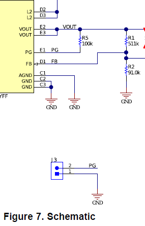
  • ahh. I thought the jumper J3 disconnected meant PG was not in play... but now I think I see whats happening on the EVM

    Can you confirm in this scenario the 63806 pulls PG low, creating a current in R5?

    @3.3V : 3.3*(1/0.1 + 1/0.6) -> 38.5 uA
    @3.0V : 3.0*(1/0.1 + 1/0.6) -> 35 uA

  • Hi Brad,

    You are right, sorry I completely overlooked the PG output. If the input voltage is present, but the device is disabled via EN pin, PG pin is pulled low. That also agrees with your measurements. If you don't need the PG output, you can remove R5 and leave PG pin floating. 

    Best regards,
    Milos