This thread has been locked.

If you have a related question, please click the "Ask a related question" button in the top right corner. The newly created question will be automatically linked to this question.

UCD3138: Question of PMBUS with ACK and clock stretching

Part Number: UCD3138

Hi TI experts,

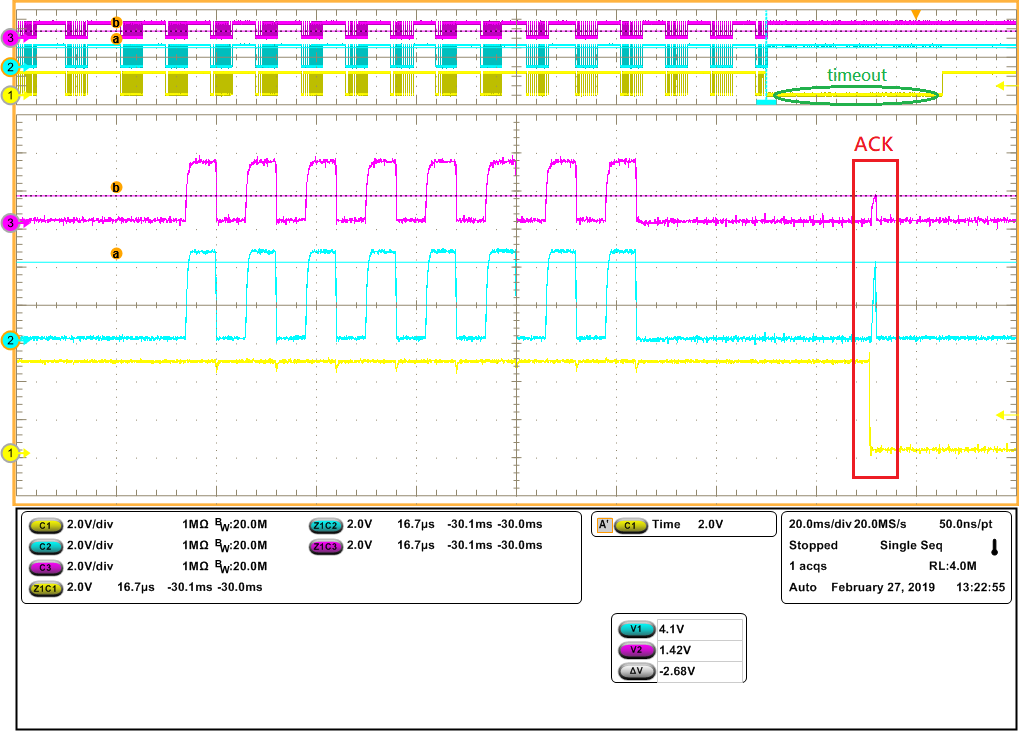
I use UCD3138 test PMBUS write with microchip pickit serial analyzer. UCD3138 is slave, microchip pickit serial analyzer is master. I found if UCD3138 pull low clock before the ACK, the ACK clock is short. This condition only happened at every 4 byte(Not including address).

please see the waveform as below,

ex: write data [S_][B6][48][D0][39][4D][2E][53][41][30][35][P_]

So I want to implement that UCD3138 don't pull low clock before the ACK, how can I do?

And I want to implement PMBUS with interrupt, how to configure the register and firmware?

Thanks!

  • It's very difficult to prevent some clock stretching.  The stretch is caused by the hardware waiting for the firmware to take the data from the receive buffer and ACK it.  

    You only have half a PMBus clock cycle to respond, if you want to do so.  I can't really tell what your clock frequency is - can you tell me what the time scale is on the zoomed in screen?

    At 100 kHz, you only have 5 microseconds.  At 400 kHz, you only have 1.25 microseconds.  With the need to have fast interrupts for other things, this means that you really can't avoid at least some clock stretching. 

    Most micro controller systems have to have clock stretching.   It doesn't seem to cause any issues with the communication anyway.  

    I think that the short clock is something caused by the way the Microchip handles the clock, since the UCD releases the clock when it gets the ACK from the firmware. 

    Without knowing the PMBus clock speed and the Microchip requirements, it's hard for me to say whether the short clock is dangerous or not.  

    One thing I would suggest is using a pull up resistor of about 1.5 Kohm.  Your rising edges look like they may be a little slow.  We have found that a 1.5 kOhm resistor is good for protecting the PMBus from noise and other issues.   

  • Hi Ian, 

    Thank you for supporting. The clock is 100KHz. 

    I think to configure the fast interrupt with trigger DATA_RDY to take the data from the receive buffer to reduce the clock stretching, is the method possible to implement?

    Thanks!

  • Tina, if you can dedicate the fast interrupt to PMBus only, you still may not be able to avoid the clock stretching entirely.  And you will sometimes slow down the standard interrupt response, especially if there are things which are called by the PMBus function that are complicated.  The PMBus functions are not written to go into the fast interrupt, and it would be relatively difficult to put them there.  To try to make if fast enough, you will need to precalculate all monitoring information, and have the fast interrupt just return the pre-calculated values.  You may also need to take all commands that change things in the UCD and put their code in a state machine in background, with the PMBus fast interrupt just setting a bit and storing information to tell the background what to do.  

    If you are using the fast interrupt for other things, it won't be interruptible, so in that case you will still get clock stretching whenever the PMBus occurs with the fast interrupt.  

    Also note that our PMBus functions are not designed to work from interrupt, so there may be issues if you use the PMBus interrupt to generate the fast interrupt.

    In addition, adding any additional interrupt function adds to the possibility of having broken writes and other asynchronous conflicts between the different interrupt levels.  These are very hard to test for, and very hard to debug, as they only occur when two levels of code interact at exactly the wrong point in time.  The interrupt has to occur while the lower priority task is in the middle of modifying the same thing.  

    Unless there is a real problem with clock stretching, we do not recommend an interrupt driven PMBus.  It doesn't seem that there is a real problem.

  • Hi Ian,

    I only use PMBus interrupt in boot code, so I don't need other standard interrupt and other fast interrupt. I use the microchip pickit serial analyzer to test pmbus wirte that cause SDA timeout because the ACK clock is short. 

    See the waveform as below,

    CH1: Master SDA, CH2: Master SCL, CH3: UCD3138 SCL

    I know that the short clock is caused by the way the Microchip handles the clock, but I need to use the microchip pickit serial analyzer to implement firmware upgrades.

    I configure the PMBus interrupt, but it isn't interruptible. Where do I ignore?

    What register is PMBus interrupt flag? And how to use the PMBus interrupt flag to enable and clear the PMBus interrupt?

    Thanks!

  • Tina, I'm not sure what's going on there.  What address are you using for the UCD.  Make sure that you don't use address 0xFF, that can cause problems somtimes, and it's not permitted under PMBus.  

    If you really want to use interrupts for PMBus, you need to look at the UCD3138 Technical Reference Manual in the PMBus section.  

    You'll see the PMBINTM register where you can enable the interrupts.  

  • Hi Ian,

    I want to use fast interrupt in boot code, but I can't implement. I find the boot sample code load_64.asm is different with the AP code. I think I can't implement fast interrupt in boot code because load_64.asm don't configure fast interrupt. 

    How can I configure the boot code?

    Thanks!

    d1d4 boot flash 001.zip

  • The only thing the load.asm does is to link the vector for the fast interrupt to the fast interrupt function.  But that is going to be a problem for you.  

    Because the boot flash normally links the fast interrupt to the fast interrupt in the main program.  

    .sect ".vectors"
    .state32
    B c_int00
    B vec_2
    B vec_3
    B vec_4
    B vec_5
    B vec_6
    B vec_7
    B vec_8


    The normal load.asm links to the fast interrupt directly:

    .sect ".vectors"
    .state32
    B c_int00
    B _undefined_instruction_exception
    B _software_interrupt
    B _abort_prefetch_exception
    B _abort_data_fetch_exception
    B _abort_prefetch_exception
    B _standard_interrupt
    B _fast_interrupt

    So you'll have to put the branch to fast interrupt in the boot vectors.  Which means that the fast interrupt will have to go into the boot area as well.  but you still need to support the fast interrupt in the main program as well.  So you really need to vector to a location which has a RAM vector which you load to branch either to the fast interrupt in the boot flash, or to vec8.  This will slow down your fast interrupt.

    I know that you are seeing the issue after a clock stretch, but I'm still not convinced that this is the root cause.  i would suggest that you put in a low value resistor, maybe a 100 ohm, in the data and clock lines between the two chips.  That way you can tell which device is pulling the line down.  Also, please try 1.5 Kohm pullups as well.  What pullup resistor are you using now?

  • Hi Ian,

    Thank you for supporting. The pullup resistor is 10 Kohm. I try 4.75 Kohm that can improve. But the pullup resistor 10 Kohm is defined by our customer, I can't change the pullup resistor.

  • Tina, the UCD will definitely not work with a 10 K Ohm resistor.  We recommend at least down to 1.5 Kohm.  10K may work with some devices, under some conditions, but for reliable operation under all conditions, and with all UCD devices we recommend a lower value.  It cannot be solved with fast interrupt.  

  • I'll assume this is resolved.