This thread has been locked.

If you have a related question, please click the "Ask a related question" button in the top right corner. The newly created question will be automatically linked to this question.

LM5176: PMP21278 300W Buck-Boost

Part Number: LM5176
Other Parts Discussed in Thread: PMP21278, , PMP, CSD19502Q5B

Hi Ti Team

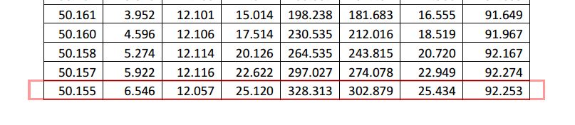
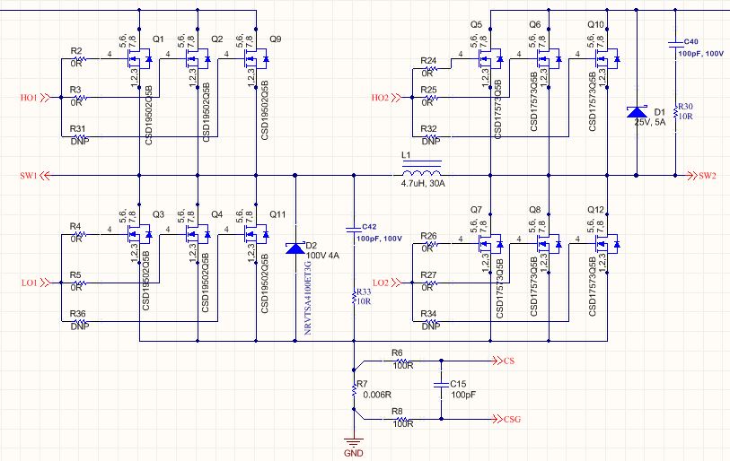
The power Loss of PMP21278 300W Buck-Boost Eval board for Vin=50, full Load is equal 25W

and power Loss of for Vin=12, full Load is equal 10W.

On the other hands, Thermal shot for Vin=12, full Load tell us  Mosfets and Inductor for 10w power loss

have High Degree.

could u tell me this eval Board How Can manage the thermal of power loss at Vin=50, full Load (25W loss)?

and Does PMP21278 300W Buck-Boost need Forced airflow?

because Im going to design a board for

Vin=9~55V

Vout=13.6

Iout=10A

and with out forced airflow for thermal management and LM5176 is in my mind.

thanks.

  • Hi Kasra,

    Thank you for considering the LM5176 and also the PMP21278.

    The test report of the PMP design is just showing you that the LM5176 itself can deliver 300W, but you may need to take additional measurement to handle the thermal issue. You are right that you may have the forced air cooling or other method of thermal solution, like better heat sinking of the power MOSFETs.  Adding headsink to the MOSFETs is one option.

    Wish this clarifies.

    Best Regards,

    Youhao Xi, Applications Engineering

  • Hi Youhao Xi

    this my Power Section Schematic

    Due to Vin=55V, Buck Mosfet (CSD19502Q5B) are selected with Vds=80V(I didnt Find better mosfet with this Cost and Low RDSon and Package)

    but this Part number has Big Qrr (Reverse recovery charge)=275nc

    and long trr (Revers Recovery Time)=72ns.

    trr is slower than dead time of Lm5176=50ns.

    Schotkey diode 5A for handling Dead time current and decreasing trr has been paralleled with Low side Mosfet of buck leg. this Schotkey diode has 25ns Revers recovery and Qrr value is not specified in the data sheet.

    on the other hands, Qrr=275nc makes Ploss=Qrr*vin*f=275*54*300khz=4.5watt loss and other loss such as  conduction and switching loss makes to have 7watt loss.

    To Decrease Qrr i try decrease current of Body Diode mosfet so Parallel 3 mosfet (one of them is reserve because limit of 3A gate diver of Lm5176).

    but i dont know effect of Current on Qrr and i cant find any note about this, in addition, Schotkey diode 5A  has been paralleled with mosfets

    about your suggestion, heat sinking of mosfet:

    I have never seen heat sinking for this package mosfet. Special structure of SON package (With out any directly attaching die to exposed pad  or Dual Cool  SON package )

    give a heat removal path Frome terminal pad to the PCB as shown in Fig 2. a s result i don't think Heat sinking this package can be effectively way.

    Fig1

    Fig2

  • Hi Karsra,

    First, refer to the article at the below link for the reverse recovery.

    https://www.vishay.com/docs/84064/anphyexp.pdf

    Parallel more MOSFETs may not always help in efficiency, because the switching losses will be increased.  I usually do not recommend parallel more than two FETs.  If two paralleled FETs do not support your application, then you need to consider large sized FETs like D2PAK, to relieve the thermal burden. The larger sized FET has a reason to exist and mainly for the thermal capability.  

    The heatsink shown in you picture can be a solution.  You need find a way to attach the heatsink to the body of the FETs, like adding to mounting holes on the PCB to hold the heatsink on top of the FETs.  Thermal grease can be applied between the FET body and your heatsink for better heat transfer. 

    Thanks,

    Youhao

  • Hi Youhao

    I will post outputs of my design board

    thanks a lot

  • Please follow the layout guidelines in the datasheet, and also reference to our EVM layout.

    Thanks