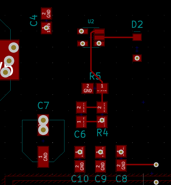
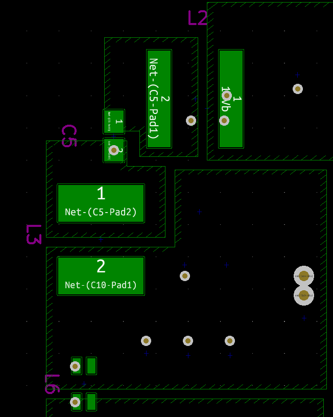
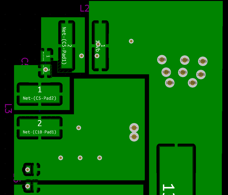
I'm noticing some very odd behavior with my design for the LM2611. I'll give you some quick specs:
L1: 22 uH
L2: 47 uH
Cin: 22 uF
Cout: 23.1 uF (three caps, one 22 uF, one 1 uF, and one 0.1 uF)
Ccuk: 2.2 uF
Vin: 13 V - 13.9 V
Vout: -13.5 V
Iout: 1 A
The power structure of this project is a bit complicated. There are a lot of different power rails for different purposes. Vin is 18 V, which solely supplies a switching buck converter which powers this regulator (and several others).
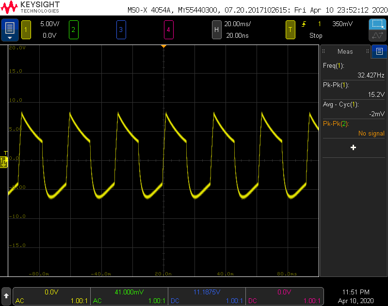
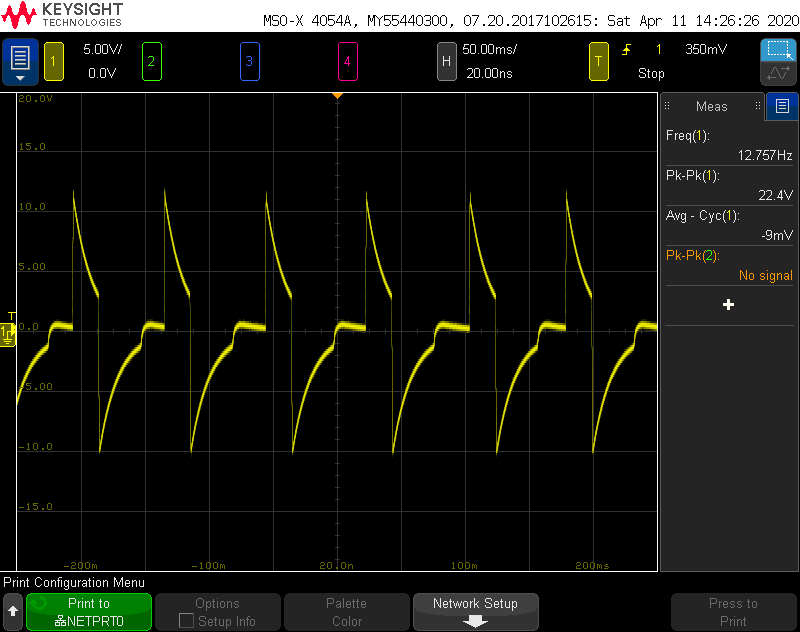
The first thing I noticed is that the switching freqency is very low. With no load, it's only 500 Hz. As you increase the load, the switching frequency increases. One of the inductors rings, so it's well within the audible range. When the load is greater than about 600 mA, the waveform at the output is radically different. You can see the waveform below. Obviously this is not how the regulator is supposed to work. Note that the frequency is only 32 Hz, and Vp-p is 15.2 V!
When the load is around 550 mA, the regulator erratically switches between this, and the expected waveform.
Does anyone have any idea what is going on here?
Thank you!


