This thread has been locked.

If you have a related question, please click the "Ask a related question" button in the top right corner. The newly created question will be automatically linked to this question.

BQ51013B: Output Power lost Spikes with increased output Load

Part Number: BQ51013B
Other Parts Discussed in Thread: BQ51010B

Hi,

I am fairly new at this Air Charger and have developed a PCB design that uses your reference design of the BQ51013B-EVM764 Evaluation Module.

After some rework on the PCB, I was able to get the unit to power up and tested under a load of 1 Amp.

The problem that I am facing is that the output power has small power loss spikes that cause my battery charger to shutdown due to the UVLO Built in "Under Voltatge Lockout" Circuit.

Putting a scope on the output showed no spikes at 100 mA loads, but has the load increased, the spikes started showing up.

Here is the circuit that I am using,

The Coil used had a Ls' of  14.3uH  and  Ls  of 15.36 uH   R= 0.255 Ohm  Using the formulas provided in the documents I came up with the above values for the caps.

Now Vout is stable and clean at 100 mA load, but I start getting these voltage lost spikes when I increase the load to above 200 mA to 1000 mA.

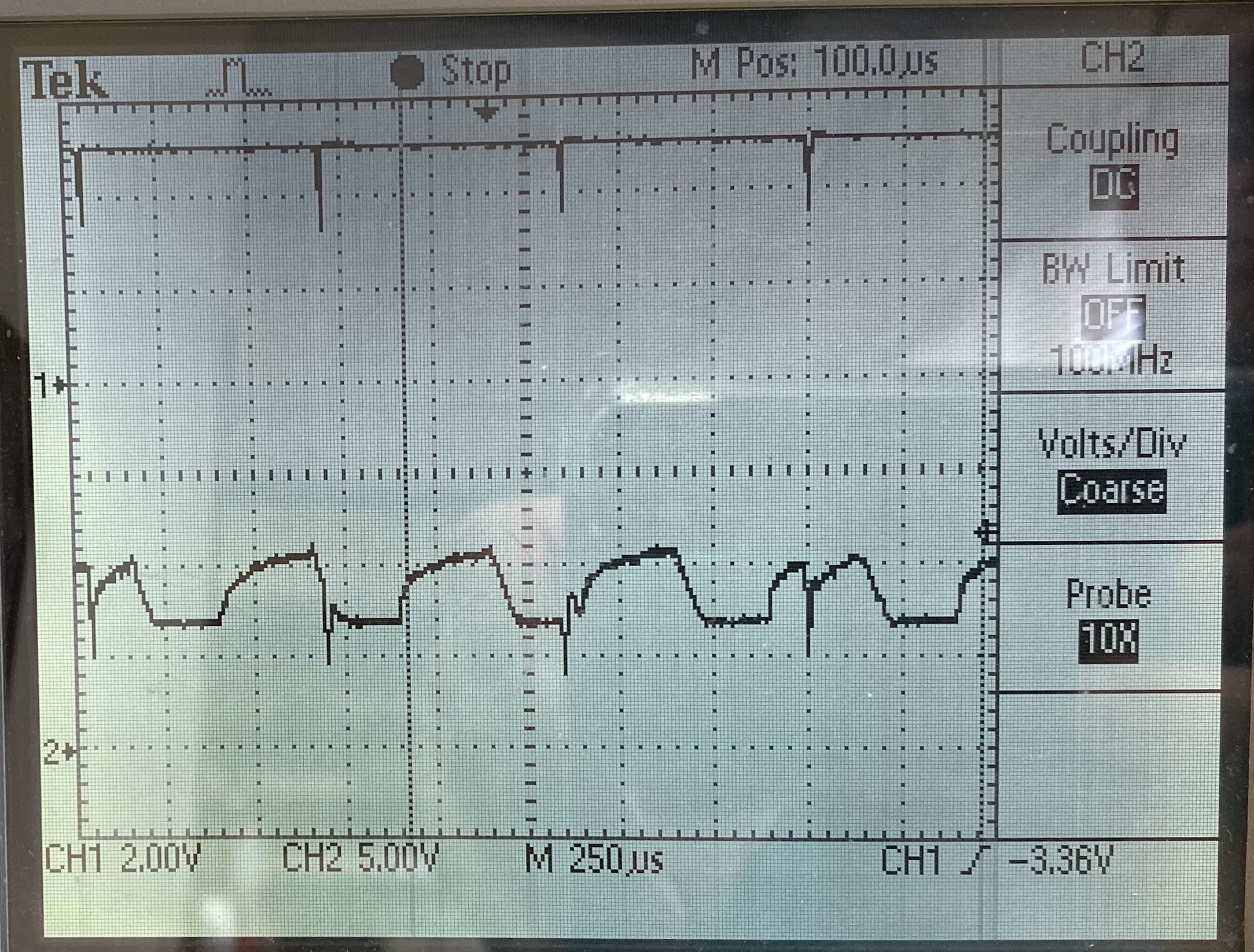
This is the result when I put a 200 mAmp load to the output.  The output starts to get these voltage drops spikes? 

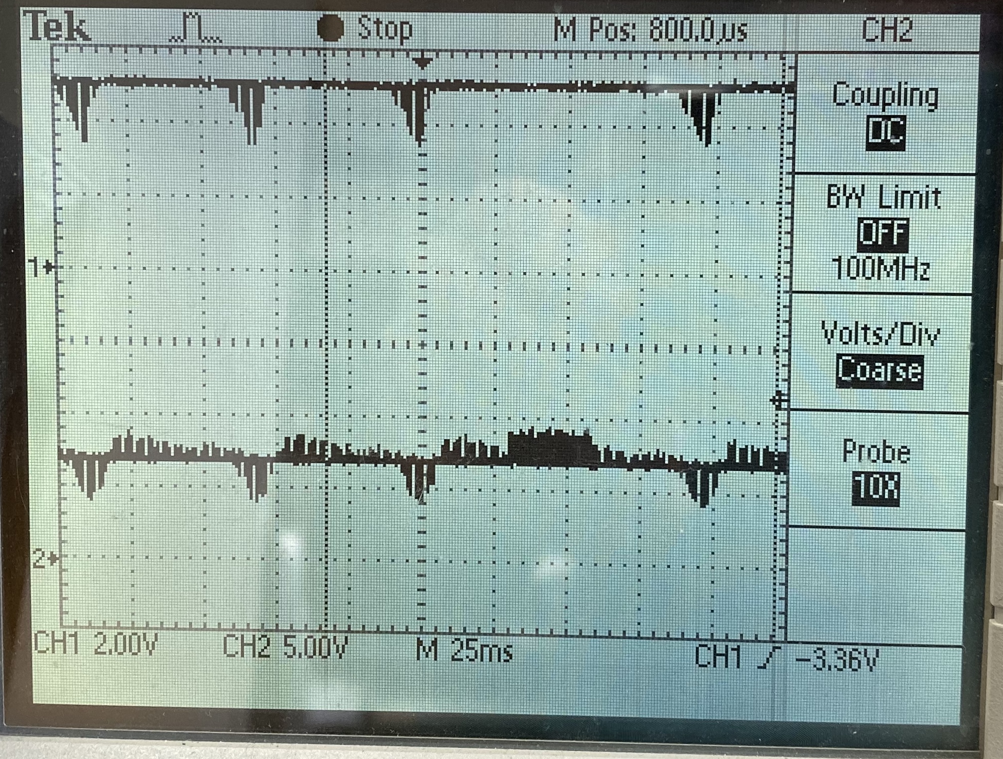
It does get more frequent as you add more load to the output.  Here I have 500 mAmp load and the output looks like this:

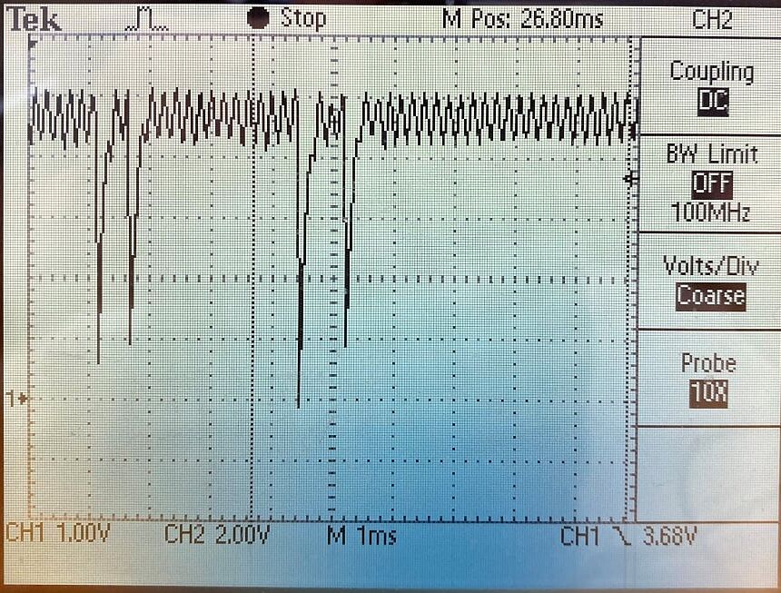
It Seems more frequent as I increase the load on the output.  The voltage does drop a little as to be expected when I increase the load, but the trouble I am having is how to remove these spikes.

I've replaced all the 10 uF caps and tried higher caps, it seem to have caused a slow down on the boot up process but did not remove the spikes. 

I'm not sure what I should be changing to try to fix this... Your help to this would be greatly appreciated.

Steve

  • Hi Steve

    Take a look at voltage on RECT pin vs OUT pin.

    Possible problem is the RECT voltage will drop during comm and output voltage will dip.  Note that comm packets are sent every 250mS.

  • Hi Bill,

    The Out voltage signal looks about the same as the RECT voltage signal.  My problem is that this Drop in Voltage spike puts any battery charger in Shut Down due to the UVLO built in circuit.

    Reviewing the example circuit provided with the TI Chip specifications, It also shows a battery charger sample circuit, to which the charging chip used also has a UVLO circuit. I believe this is also going to have the same problem.  HOW did they get around this?  

    Is there something I can add or change in my circuit to resolve this?  

    I really need help to resolve this, I have a team waiting for my power module for a portable unit that we are developing.

  • Hi Steve

    I was trying to get a better understanding of the voltage loss spikes that are causing the UVLO to trip.

    It is common to see dip in RECT voltage caused by the COMM capacitor.  Often at light loads they will have a Boost effect and at higher loads a Buck effect dropping the RECT voltage.  At higher loads the RECT voltage is reduced so that power dissipation on the RECT to OUT ldo is reduced. 

    Dip in RECT voltage  during comm can possibly be helped by reducing by reducing comm caps, schematic shows 33nF.  Have you tested with 22nF.

    If the dip associated with  output load step?  The ILIM will set output current limit of the LDO. Adjusting the ILIM may help. 

    R4, 20k resistor between RECT and FOD can be removed for now.

  • I also have to note, that at 100 mA load, the circuit does not produce the voltage lost spikes, Only when the power is increased over 200 mAmps - 1 Amp  do we get these voltage lost spikes. The higher the current the more spikes we get and the spike tend to drop lower in voltage value closer to  zero volt.

    I do think there is a solution for this, because in my efforts to take measurements of the circuit, the circuit randomly started to charge at 800 mAmp and the spikes stopped?!?  I was unable to reproduce this more then once, but the fact that it did work, until I removed the coil from the source.

  • Hi Bill,

    Once again, thank you for your assistance to this project. I have replaced the two Capacitors of 33nF C4 and  C13 with a 22 nF cap as suggested and also removed R4 the 20K resistor.  Here is what Vout (CH1) on the top and RECT(CH2) on the bottom wave forms at 100 mSec  looks like now.

    I noticed that the Spikes on Vout have more drop and RECT has a higher Voltage.  I've taken faster captures of the same output, at different  time areas on this image.

    The above wave forms are taken with the circuit  connected to a Battery charger circuit which does not engage due to the UVLO circuit.  the Power spikes turns off the Battery Charger and it never really kicks on. I did put a constant load on the output and at 100 mA is has no problem, little if any power spikes shown, as I increase the load, the power spikes kick in.  The Load can go up to 1 Amp no problem, but lots of power spikes. See my previous Vout shoots.

    The Snap shot below is Vout and RECT with the 33 nF caps and the 20K Resistor still on.  The spikes Voltage is less on RECT.

    Now I know you asked me to change ILIM.  Changing R3 or R2 or both?  I have two resistor ladder switch boxes in 1 Ohm increment 1% 1 Watt that I can use. Should I increase or decrease which resistors... What should the Max resistance be?  How should I go about this to start?  What load should I have on Vout?

    Thanks

    Steve

  • Hi Steve

    The scope captures are showing a couple of things:

    1.)  The dip in VOUT and RECT are occurring at the same time.  Also the RECT voltage is at 7V indicating a light output load. 

    2.) COMM pulse is not causing issues, the dips are not at that time.

    3.) ILIM setting is not an issue.  If it were we would see a dip at VOUT and not RECT.  --- R2 66 ohms and R3 196 ohms is OK for now.

    With a wireless system the load step needs to be supported by RX Coil, response time is to slow to change operating point.  We expect RECT to drop some during the load step but should be above 5V and output does not dip.

    Something to consider is the BQ51010B, this is a 7V output device that is P2P.  Can the charger accept 7V input?