This thread has been locked.

If you have a related question, please click the "Ask a related question" button in the top right corner. The newly created question will be automatically linked to this question.

LMG1210: Half-Bridge Capability

Part Number: LMG1210

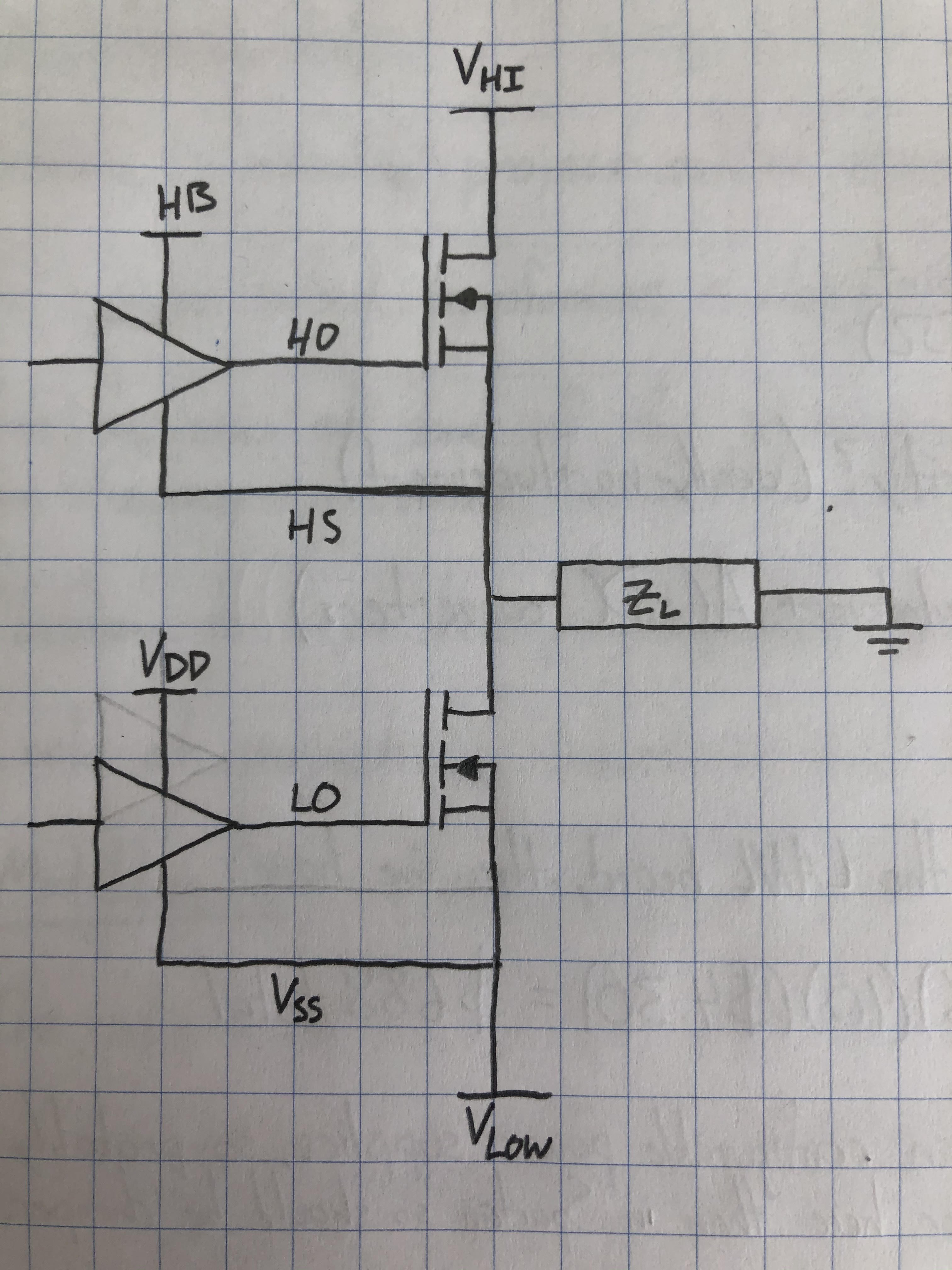
I wanted to confirm that this part (familty) works with a true half bridge (the simple figure in the LMG1210 datasheet does not show the negative capacitor)? In other words, does VSS need to be ground or can it be a negative voltage (say -200 V)?  I'm thinking the only thing that matters is the difference between V_HS and VSS, but I'd like to double check.  And insight would be greatly appreciated.

Matthew Bartone

  • Hi Matthew,

    Thanks for reaching out on e2e. You are correct, besides the HS voltage (without a bootstrap diode) the negative voltage capability of lmg1210 is limited by the HB-HS voltage as well as the bootstrap diode forward voltage, however if no bootstrap is being used then the HB-HS voltage should remain at about 5V for the high-side drive. For example, using a bus voltage (while VSS= -200V) then a bootstrap diode cannot be used (due to bootstrap diode forward voltage rating being out of spec). If HS is at -200V, then HB should be at -195V. If needing to power the high-side FET without a bootstrap, you need an isolated supply for HB-HS (for example a LDO to replenish HB with respect to HS) while floating the BST pin. Let me know if you have any questions.

    Thanks,

  • Hello Jeffrey,

    So have some follow up questions.  Here's a quick circuit diagram of our half-bridge and how it would connect to an LMG1210

    Half Bridge Circuit

    For the LMG1210, what are the maximum values V_HI and V_LOW can be  (for our application we want V_HI = (-) V_LOW), and consequently what would VDD and HB need to be?

    And would we still need isolated power (for HB and VDD)?

    Many thanks again for helping out with all of these questions!  Very much appreciated.

    Matthew Bartone

  • Hi Matthew,

    Thanks for the follow up.

    Since 1210 is a 200V part HS-VSS can operate up to 200V which means VHI - VLOW = 200V. For example if VHI = 100V then VLOW can be as large as -100V. In this case, VSS would be -100V so VDD would need to ne -95V. The input signals would also need to be level shifted to be with respect to VSS or -100V in this case. HB would be riding on HS and HB-HS needs to be 5V. The bootstrap diode would see -95V on the anode from VDD and during high-side on-time the bootstrap cathode would see +105V from VHI+(HB-HS). This will blow up the diode due to the large reverse bias therefore a bootstrap diode cant be used in this case and an isolated supply for HB-HS would be needed, The -95V VDD supply does not need to be isolated however it does need to be with respect to VSS. Let me know if this helps answer your question or you have any more.

    Thanks,