This thread has been locked.

If you have a related question, please click the "Ask a related question" button in the top right corner. The newly created question will be automatically linked to this question.

BQ77905: 7S recommendation

Part Number: BQ77905
Other Parts Discussed in Thread: BQ77915

Hi,

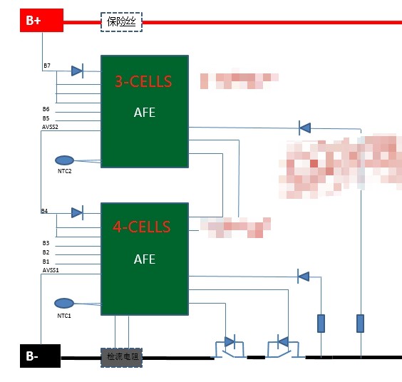
My customer has a 7s application. They are evaluating BQ77905.  only protection need due to cost and power consumption.

but there is a unbalance and power consumption concern when stacking up BQ77905.   Please kindly give your suggestion for these concerns. thanks. 

specific concerns when stack using 2 BQ77905,as below:

1. if this will cause different core loss between top and bottom  if long term operation.

2. is there a test data about the battery core loss difference based on typical circuit? any suggestion for this unbalance case?

BTW, to reduce the power consumption, if it is OK to increase the resistor value  between GS pin of MOSFET. so far used the recommended 1M. 

can this be increased to 3M or more? 

  • Hi Yue,

    1. Yes, different loading in the stack configuration can cause an imbalance in cells.  See https://www.ti.com/lit/pdf/slua774 figure 8 and the related discussion for adding load matching resistors RDLD and RCLD.  With 3 and 4 cells in the different devices the drive voltage mismatch will need to be considered, see figure 9.

    2. I don't know of a study.  You can calculate for the time you expect the battery to operate at each voltage. 

    3. RGS can be adjusted.  Since it is RGS which completes turn off of the charge FET after PACK- falls sometimes you want it small, sometimes you want it large, see the BQ77915 data sheet figure 26 and comments in 10.1.1.4.  In some cases you may want a circuit to turn off CHG such as https://www.ti.com/lit/pdf/slua773 figure 6, note the load resistance will have a limit with the parallel resistors.

  • Thanks for reply. Could you please furhter comment if discharging related resistor  meet the the same rule as charging.

  • Hi Yue,

    DSG drives high and low, the FET source does not go significantly above or below GND, so DSG will not normally need such a circuit.  Usually a resistor is sufficient, Sometimes a diode is used with a different resistor to turn off more quickly than turn on.