This thread has been locked.

If you have a related question, please click the "Ask a related question" button in the top right corner. The newly created question will be automatically linked to this question.

TPS25982: doesn't power up with load

Part Number: TPS25982
Other Parts Discussed in Thread: TPS2663

Hello,

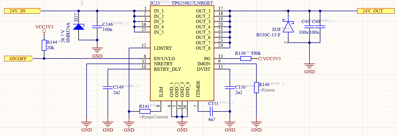
I have problem with TPS259827LNRGET. It doesn't power up with any load current, even small like 1A (still retries, NRETRY connected to GND), but there is no problem with powering up without load (which can be applied after). Vin is 24V and max current is 6.5A (about 1A during powering up), load capacitance 100-200 uF. More details: LDSTR connected to GND, EN pulled up to external 3V3 with 10kOhm resistor, retry_dly cap 2n2, Rilim 191R, Rimon 1k69, Cdvdt 2n2, Citimer 4n7, PG puled up to external 3V3 via 100kOhm.

The question is, what is wrong?

I was using your dedicated calculator, but I still don't understand why it doesn't work.

  • Hi,

    The maximum recommended operating voltage of TPS25982 is 24V. We don't recommend using this device for 24V nominal voltage as the maximum input voltage can be > 24V.

    Can you please share the design calculator with your design parameters filled in and your schematic for review. 

  • Hi Praveen,

    Schematic is following:

    Where RmaxCurrent is ~250R (270R probably) and Rimon is 2k2.

    For Cdvdt = 2n2 fuse powers up with max 0.8 A current load. It's not enough. In the table on p.9 in datasheet margins are wider. In the excel file I'm setting 10R load at start-up. Anyway, I minimized dvdt time (removed C150) and here we have another problem. As you can see, I'm trying to control EN line from MCU. When I'm setting low state (connecting to GND) on this pin during efuse operation with some load, after reset try, it destabilizes and falls into infinite reset cycles. I'm getting voltage on the output only if I turn off the load.

    Here is efuse power up with no load (blue - EN pin, pink - output voltage):

    I thought the problem can be with the external 3V3 source (it's coming from DC converter which is powering from 12V, which in turn come from 24V). I've noticed that if I turn off 24V power supply and turn it on fast enough (so supply on EN pin won't fall under ~1.2V) efuse will power up with load. Below is oscillogram.

    Second channel div is 1 V (EN pin) and third one 10 V (output voltage). First rising edge is the first PCB start-up - fuse is resetting all the time. I'm turning the power supply off and turning it on fast - fuse works fine. The third rising edge shows the situation when I let 3V3 on EN pin fall too much - efuse is resetting again. It doesn't make any sense - how EN function suppose to work if I can't set low state on this pin (<1V2)?

    PG pin works correctly - high state if fuse power up and low if not (reset cycles).

    I was trying also to use a voltage divider instead of using external 3V3. According to your eval board schematic it looked following:

    I've changed R2 to 60k, so EN voltage was ~1.35V. When I was switching line to GND to reset fuse, it didn't power up correctly and was resetting infinitely, again. Still under the load of course.

    While fuse is resetting we can observe voltage peaks on IMON pin (current load 2.9A, Rimon 2k2):

    What is wrong here and how can I solve this problem?

    I've attached excel file.

    Regards,

    Margo

  • Hi Margo,

    It is possible that the device TPS259827L does not start with load when you are operating at 24V. This is because of the following reasons,

    • As the input voltage is high, the power dissipation across the FET will be high for smaller current as well. The total current in the efuse will be sum of load current + current flowing into the output capacitors. 
    • As you can see in cell D7 of the attached design calculator, the design will not have a succeful startup with 24V and 10 ohms load during startup and 2.2nF dvdt cap. 8053.TPS25982xx_Design_Calculator_RevA.xlsm
    •  The design calculator takes into consideration the 'Time to Thermal Shutdown vs Power dissipation' curve/data which is taken on the device EVM. The EVM can have different RQJA when compared to your system and most probably the RQJA on your system would be less than that of the EVM. In this case, the device will take even less time to hit thermal shutdown and hence will support less load current than what the design calculator suggests.

    As I mentioned earlier, this device is not suitable for operating at 24V nominal voltage. As your system specs are 24V and 6A, you can consider using TPS2663. The TPS2663x devices are easy to use, positive 60 V and 6-A eFuse with a 31-mΩ integrated FET

    Product Folder: http://www.ti.com/product/TPS2663

  • Hi Margo,

    Hope your questions are answered. In case you do not have any other questions, can we close this thread ?