This thread has been locked.

If you have a related question, please click the "Ask a related question" button in the top right corner. The newly created question will be automatically linked to this question.

TPS2491: Unexpected shutdown?

Part Number: TPS2491

Team,

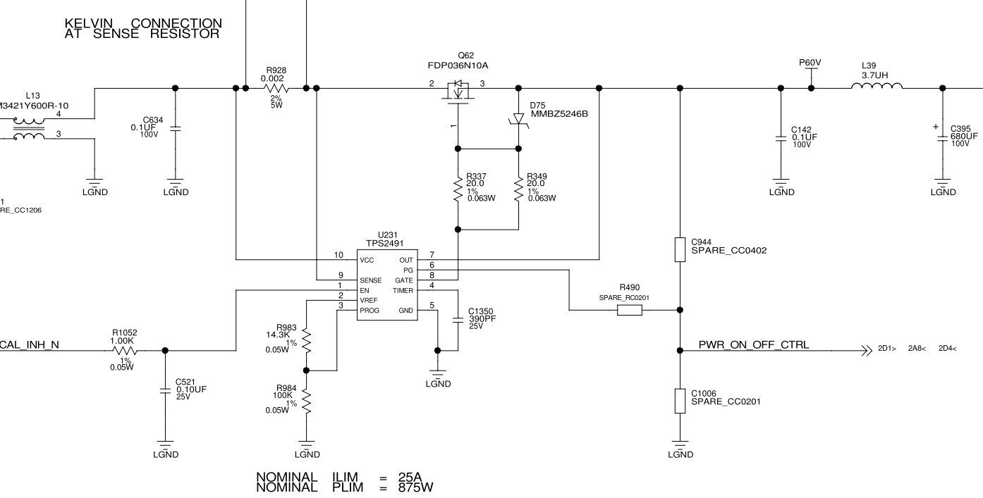
The description in the datasheet indicates to use a gate drive resistor of 10 Ohms if CISS is above 200pF. The MOSFET we have chosen is the FDP036N10A which has a very large CISS (5485pF). For this size of MOSFET, is it necessary to have a lower gate drive resistance?


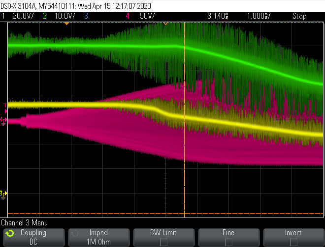
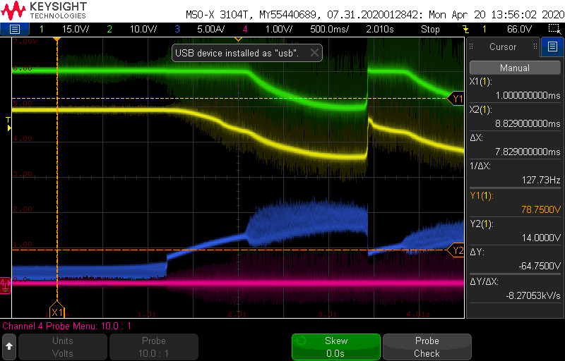
The second query we have is related to an unexpected shutdown that we are seeing. After the FET is fully enhanced, our system begins to draw power and we observe the gate on the FET start to drop unexpectedly. This is not a hard turn-off as seen in other situations. The gate takes about 1.5msec to drop to a point where current is shut off. Do you have any suggestions for what may be happening here?

  • Hi Julio,

    10 Ohm gate drive resistor is enough. Can you please share me the schematic and filled up design sheet for review. The design sheet is available at http://www.ti.com/product/TPS2490/toolssoftware

    What is the type of load ? Is it pulsed in nature which momentarily exceeding the set current limit ?

    Can you share the test waveforms

    1. Vin, Vout, Timer, GATE
    2. Vout, GATE, Timer, input current

    Best Regards, Rakesh

  • Rakesh,

    I can comment as this was the issue that I raised. I've attached the schematic and some scope captures below: 

    The load is a ramp of current up to a steady-state value. The issue occurs during the ramp. I have a few scope captures that show the waveforms you are looking for. The first shot below shows an overview of the issue with the input and output voltage (yellow is input voltage, green is output voltage, blue is input current). 

    The gate voltage (yellow) can be seen in this next image to drop just before the output voltage drops (green). 

    The next scope shot includes the timer cap voltage and shows the same condition (yellow is timer capacitor voltage, green is output voltage, blue is input current). Since the timer capacitor is not pulsing when the controller first shuts off, I'm assuming it is not in a current limit or power limit scenario. 

    I have been able to run in other scenarios with higher current than what is shown here without the controller shutting down. In this case, the controller seems to be shutting down near 5A with the current limit at 25A. 

    Is there a state of the controller that would allow the gate to drop in such a slow manner? 

    Thanks for the confirmation on the gate drive resistance. 

    Matthew Swanson

  • Rakesh, 

    Adding the completed worksheet as well. 3007.TPS249x_8x_Design_Calculator_REV_B.xlsx

    Matt

  • Hi Matt,

    Thanks for the details. The controller pulls down the GATE for overload event. 

    Why there is so much noise on the input voltage ? Have you checked by shorting L13 and L39 ?

    What load is used for testing ? Is it e-load ?

    In your test waveform, to which node (pink) the channel-4 corresponds to ?

    Best Regards, Rakesh

  • Rakesh, 

    Thank you for the response. The red signal is a high-frequency load that I was monitoring and is the source of the current draw on the input. The final load is a resistor. 

    I have not tried shorting L39 as it is blocking switching noise from a higher power converter downstream. The output side of the controller (P60V) net has about 66uF of bulk shown on a different page. I have also not tried shorting the input common-mode chokes. Most of the noise is due to my sensing method. I had a rather large loop on my probe when I was measuring. I apologize for the fuzzy plots. 

    You've hit on one of the thoughts we have about this issue. It is placed in close proximity to a high-power switching converter that drives the load. From what I understand of the part, the 'timer' capacitor charges when in current limit or in power limit mode. However, at the initial drop in the gate voltage, the timer capacitor is not charging. i.e. I assume the part does not think it is in power limit or current limit mode. Have you any experience with these parts exhibiting strange behavior in the presence of noise? If so, would you recommend any changes to our design that may help? 

    I have attempted adding extra bulk at the input near R928 (per datasheet recommendation) and a small capacitor in parallel with R984. 

    Thanks for the help!

    Matthew Swanson

  • Rakesh, 

    One other plot that may be of use is the following one I took with the output ramping very slowly. In the image below, the gate (yellow) can be seen to drop very slowly in the time span of ~2 seconds. After this, the gate snaps back up to near where it should be and repeats the sequence. The output voltage is in green, the input current is in blue and the 'timer' capacitor is in red. 

    This seems to indicate that something is either drawing down the gate or the gate is no longer being charged by the controller during this time frame. 

    Thanks!

    Matthew Swanson

  • Hi Matt,

    In case of pulsed load at the output, the Vout ripple can couple to the GATE of the external MOSFET through Cgs and can load the GATE node. Can you add capacitance at the source of the MOSFET (100uF electrolytic + 1uF ceramic) and check. If it does not help, add 10nF between GATE to source and check.

    Best Regards, Rakesh

  • Rakesh, 

    Thanks for the tip! This got us moving in the right direction. 

    We found that current was leaking through the Zener D75 and also had an internal path through the hot-swap controller (U231) due to the noise from our downstream power stages. This leakage exceeded the 22uA (nominal) capability of the hot-swap controller. Our fix was to add a 100pF in parallel with D75 and a 220pF from pin 8 of the hot-swap controller (U231) to LGND. 

    Have a great weekend!

    Matthew Swanson

  • Hi Matt,

    Good to hear that. Let me know if you have any more questions.

    Regards, Rakesh