This thread has been locked.

If you have a related question, please click the "Ask a related question" button in the top right corner. The newly created question will be automatically linked to this question.

LM5030: Push pull converter Application circuit

Part Number: LM5030
Other Parts Discussed in Thread: UC1846

Hi TI Team,

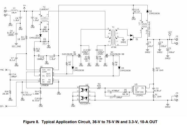
I have below query in LM5030 Current mode push pull converter application circuit.

1)Zero frequency (Fz) formed by R14 and C18 for cancel opto pole?

2)How plant and opto pole compensated by error op amp?

Regards,

Kubendran

  • Hello 

    Your question refers to Figure 8 of the LM5030 data sheet.

    R14 and C18 is a high frequency filter that is placed to eliminate any switching noise pickup on the COMP input.
    Its function is to filter out any parasitic noise pickup due to pcb layout.
    It is not part of the classical feedback network.

    Your question on the compensation method use in this application can best be answered by studying any or all of the TI seminary papers.

    These papers are located here.

    Regards

    John

  • Hi Sir,

    Thank you for your reply.  Please share any specific document for opto coupler based loop compensation. 

    I searched slope compensation like UC1846 which is differently implemented than LM5030. For additional slope compensation how to calculate required resistor value to avoid oscillation ?

    Regards,

    Kubendran

  • Hello,

    Please check the reference I have provided for the required information.

    Regards

    John