Hi team,
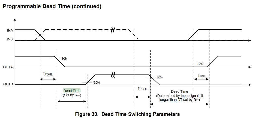
How does propagation delay affect dead time max/min value and dead time matching?
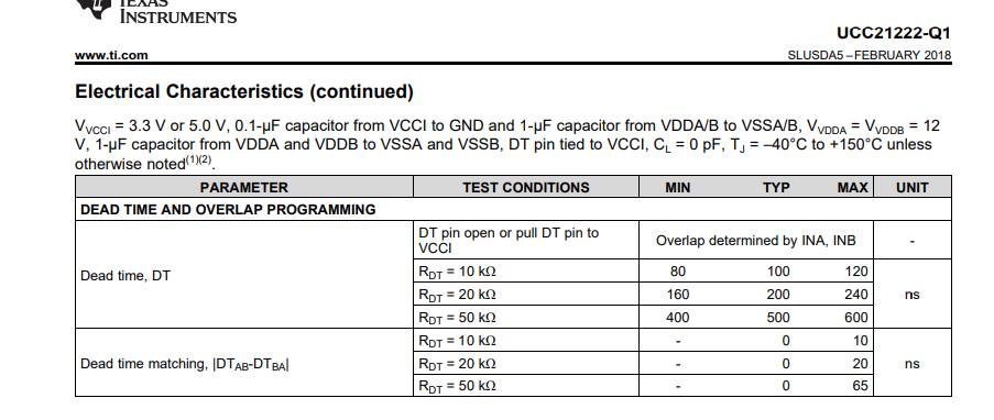
Datasheet says dead time range when RDT=20k is 160ns~240ns. Also dead time matching is 20ns max.
Do they include propagation delay, whose max value is 40ns?
Also do they include propagation delay matching, whose max value is 5ns?
In addition, how should we design dead time with including propagation delay?
Regards,
Ochi