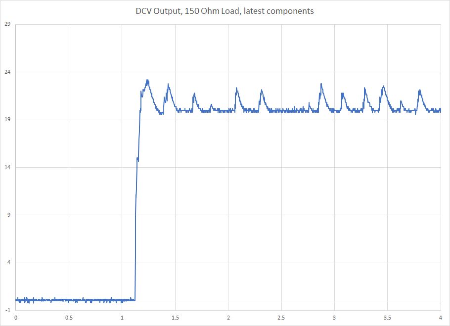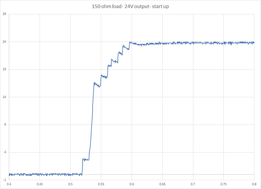
150 ohm load start up
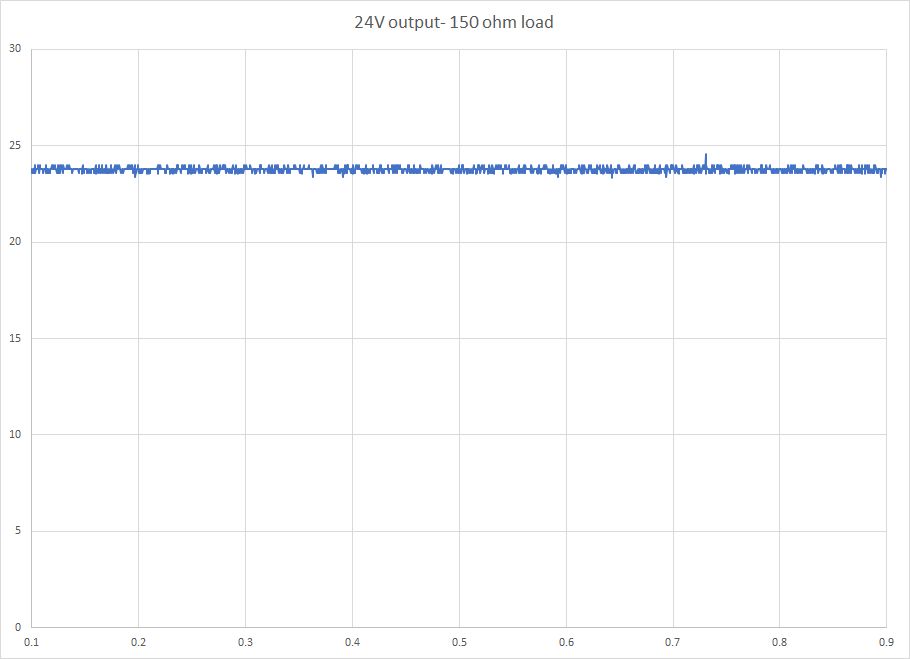
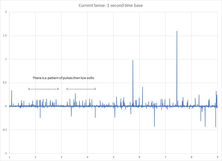
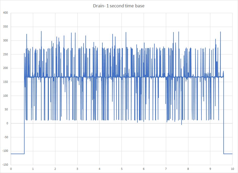
150 ohm load running

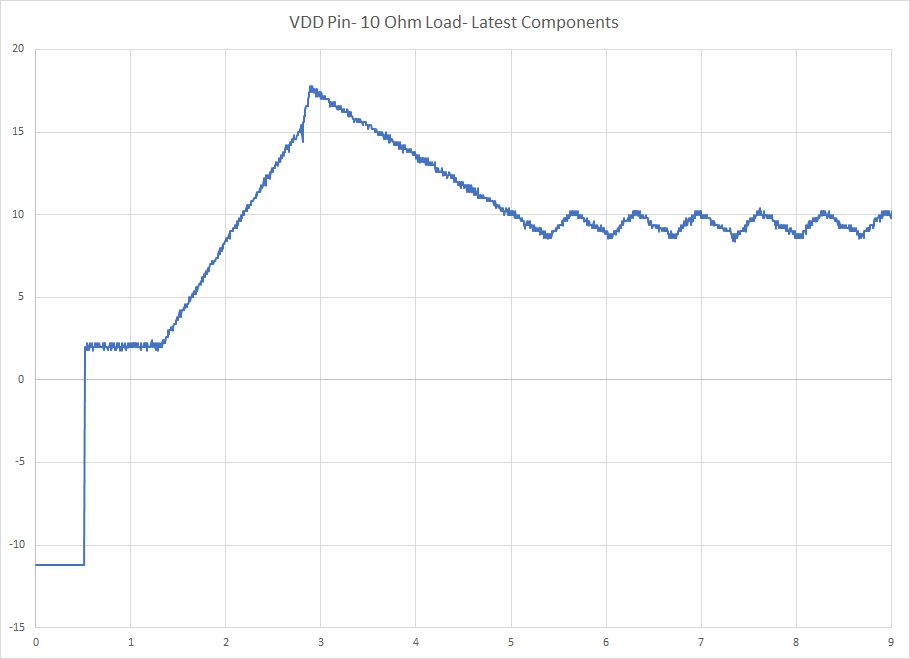
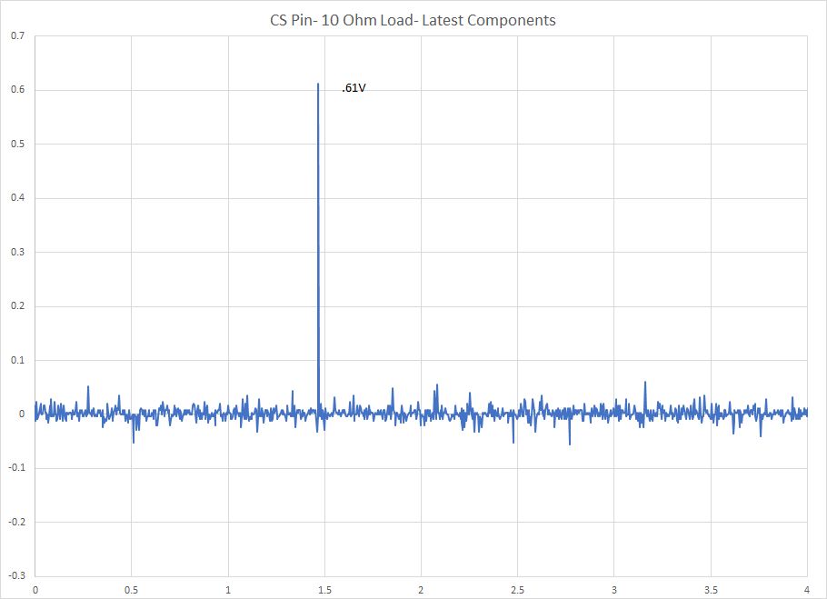
10 ohm load- output
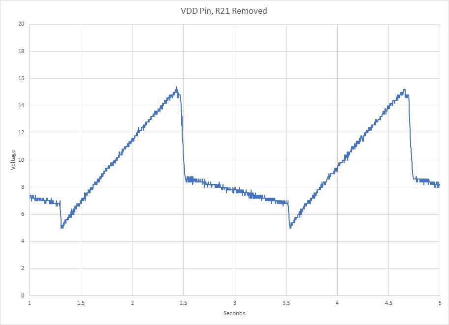
I changed the mosfet sense resistor from .12 ohm, to .10 ohm. Now output just jumps up then down.
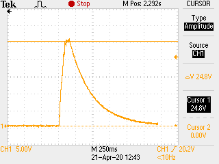
150 ohm load start up
150 ohm load running
10 ohm load- output
I changed the mosfet sense resistor from .12 ohm, to .10 ohm. Now output just jumps up then down.