This thread has been locked.

If you have a related question, please click the "Ask a related question" button in the top right corner. The newly created question will be automatically linked to this question.

TPS57114-Q1: Question about the position of the sense resistor in relation to the regulator's feedback loop

Part Number: TPS57114-Q1
Other Parts Discussed in Thread: INA3221, INA301,

Hello,

I am involved in the design of a configurable power management which current and  voltage telemetry.

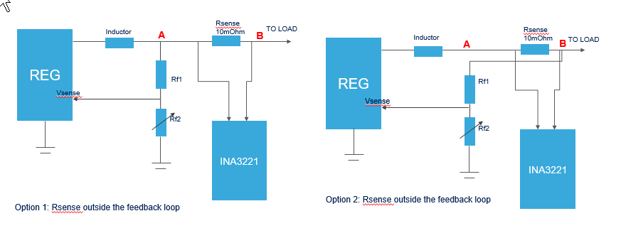
For that we are exploiting a digipot in the voltage divider and  a sense resistor (10m Ohm) connected to your INA3221 (voltage and current monitor).

I have a question about the position of the feedback loop related to sense resistor and load (a digital device with an highly variable current profile).

I believe that the optimal position for the feedback tap would be between the sense resistor and the load in order to compensate the sag that we otherwise would have if we put the sense resistor outside the feedback tap.

Can you see any drawback with this solution? What if we put the sense resistor and hence the voltage and current sense very close to the loading device? would thet be ok?

  • Hello Giulio,

    I want to make sure I understand your system right.

    Can you share a schematic of what you are trying to achieve?

    Thank you.

    Regards,

    Dorian

  • Hello Dorian,

    thanks for your fast reply.

    Please give a look at the pictures below with options 1 and 2.

    Case 2 should guarantee the regulation at the load (node B) with less ripple.

    thanks

    G

  • Hello Giulio,

    Unfortunately I cannot see the picture, I send you a request to have a private conversation.

    Once you accept I will come back to you as soon as possible.

    Thanks a lot!

    Regards,

    Dorian 

  • Hello Giulio,

    I didn't hear back from you.

    Could you upload the same image somehow differently, to make sure I understand your question?

    Or can you accept friendship request, so we can discuss via private message?

    Thanks a lot!

    Regards,
    Dorian

  • Ciao Dorian

    Sorry I somehow missed the previous messages because I had other inquiry with your forum.

    I will try to send back the picture (I did not realize that it wasn't sent correctly) and yes, I am pleased to accept your friendship request..

  • Buongiorno Giulio,

    In general to avoid noise on the feedback trace from affecting the feedback loop, we recommend to keep Vsense connections short and directly connected at a stable voltage which is the output capacitor. You can also refer to the layout example we have in the datasheet (section 10.2).

    What you can do to compensate the Rsense drop knowing you are using an adjustable R2, is to aim for a slightly higher regulation point.

    Let me know if you have any other queries.

    Thanks a lot!

    Regards,
    Dorian

  • Hello,

    the problem is that the load current is not constant and with very big variations. moving the feedback point downstream the RSENSE allows the regulator to set an higher voltage, very fast,  in response to the resistor's voltage drop. Hence the output resistor seen from the voltage loop is divided by the feedback factor.

    all of this happens very fast , especially if we set an higher regulator's switching frequency, the R2 adjustment process is very slow compared to the feedback adjustment.

    Basically what I see in simulation is that after the kick related to the fast load transient the voltage is set to the desired value.

    Plus this might be beneficial because, with the proper layout, we can set the feedback tap directly on the device's supply pin.

    Regards,

    G.

  • Hello Giulio,

    I understand more challenges you are facing here.

    My concern here as Vsense will be routed further away from output capacitor is that it would add inductive path in the feedback loop and might alter compensation speed and accuracy.

    I think if special attention is brought to Layout to make sure Rsense is not too far away from output capacitor nor on the other side of the board, this should be fine. Do you have a layout, you could share here?

    Thank you very much!

    Regards,

    Dorian 

  • Thanks Dorian,

    Unfortunately I don't have any layout to share at this time, but what I can say is that both Regulator and Sensing resistor will be placed as close as possible to the rail, after the sense, the proper rail filtering will be implemented, so I can't see any serious issues.

    Do you have any layout guidelines to share?

    We are also exploiting, for the most demanding rail, a fast conversion with the MCU's internal (and very fast) ADC fed by your INA301. Max current is around 15A.

    Do you have any guidelines/suggestion for this component or maybe can you suggest something different?

    Simulations with your spice models are already satisfactory ( 10mOhm sense + INA301A1).

    Best regards,

    G

  • Hello Giulio,

    You are right having both Regulator and Sensing resistor both placed closed to IC is paramount.

    Also as feedback will not be directly connected to output capacitor, I recommend you to you use a seperate analog trace GND to link Vsense to GND.

    Looking at 10.2 Layout example from Datasheet, you can see a thin analog GND trace for VSENSE/COMP/RT/CLK) This will allow this trace to be less influenced by noise and current loops flowing in the GND planes and layers. 

    For INA301, I will let an expert on his part of the portfolio help you.

    Let me know if you have any other questions on TPS57114-Q1 and Layout.

    Thanks a lot!

    Regards,
    Dorian

  • Thank you Dorian,

    your feedback was very valuable and the layout example is crystal clear!

    Please proceed with the INA301. I got several questions to ask :-)

    best Regards,

    G

  • Hi Giulio,

    May I please ask that when you post questions regarding the INA301, you do so in a new thread? This is important so that users of the forum can cleanly find answers to specific topics in the future.

    Thanks in advance!

    Best regards,

    Ian Williams
    Applications Manager
    Current Sensing

  • Sure!

    Thank you for your support.

    BR.

    G