Because of the Thanksgiving holiday in the U.S., TI E2E™ design support forum responses may be delayed from November 25 through December 2. Thank you for your patience.

This thread has been locked.

If you have a related question, please click the "Ask a related question" button in the top right corner. The newly created question will be automatically linked to this question.

ULN2003A: Damage issue

Part Number: ULN2003A

Hi Team,

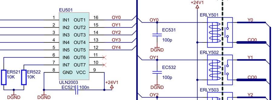
My customer uses ULN2003ADR to drive relays for PLC DO application, they received failure units returned from their end customer and the root cause of TI's FA report is always EIPD, although the fail rate is quite low that few units per year. So, customer is asking any suggestion on circuit that can improve their system's robustness, below is customer's circuit. 

Add some information, DO has two types module, relay and MOSFET. The failure units almost from relay type module. Regarding +24V1 power rail, customer have also placed TVS, line filter, XY capacitor to filter other unexpected noise or sipke.

Thanks a lot.

Vincent Chen

  • Hi Vincent,

    Welcome to E2E!

    This looks like a typical application of the ULN2003 device, and I don't see any concerns with the circuitry. I do have a couple questions concerning the output of the ULN2003.

    How much current is going through the channels for the relays?

    Are all the channels being used at the same time?

    What is the duty cycle of channels? (i.e. do they have PWM signal or stay always on, 100% duty cycle, when enabled?)

    Best regards,

    Andy Robles

  • Hi Andy,

    Thanks a lot for checking customer's circuit and application, please find customer's reply below and give us your comment.

    How much current is going through the channels for the relays?

    [Customer] The resistance of relay coil is about 5.2KΩ, the current is 4.52mA for single channel

    Are all the channels being used at the same time?

    [Customer] Yes, that’s possible, depend on customer’s application

    What is the duty cycle of channels? (i.e. do they have PWM signal or stay always on, 100% duty cycle, when enabled?)

    [Customer] The maximum frequency of relay output was limited at 1Hz, i.e the fastest response time is 0.5s to transfer next status. there exist the 100% duty

    cycle situation, also depend on customer’s application.

    Besides, one question from customer who is wondering if E pin(its connected to ground) experiences a large ground bouncing that will damage input side via internal diode?

    Thanks very much.

    Vincent Chen

  • Hi Vincent,

    Application wise the ULN2003 is not being electrically stressed by the configuration or by any load currents that are being pulled by the coils. Circuit wise there isn't anything to my knowledge that could further increase the robustness of this part of the system. Having said that, there could be other overall system events that could damage the device if anything exceeds the abs max electrical specifications of the device. One thing you mentioned was the ground bouncing which would be a system event on the ground plane of the PCB that could cause this, but that would be external to the circuit implementation of the ULN2003. Since the nature of the event seems to be random and only happen in a few units per year there isn't a way to further troubleshoot this unless the customer has scope shots at the time the event happens that over stresses the device with key signals from the circuit(i.e. input, output, VCC, GND).

    Best regards,

    Andy Robles

  • Hi Andy,

    Understood, thanks very much for your advice.

    Vincent Chen