This thread has been locked.

If you have a related question, please click the "Ask a related question" button in the top right corner. The newly created question will be automatically linked to this question.

TPS2662: Schematic review

Part Number: TPS2662

Hi,

we are having problems getting the below schematic to work robustly.

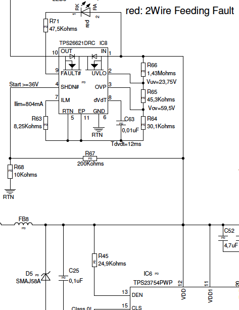
The idea is to have a PoE-PD and divert the 48-56VDC from the PoE switch to a remote sink. So for 802.3at app. 2-3W would be fed into the flyback and converted down to 12V for local supply. The remaining power would be fed from the PoE rail (48-56VDC) via the eFuse to a remote sink.

We were hoping the eFuse would switch on only after the PoE switch is supplying the full voltage and also provide power in a controlled way. However, we have already destroyed 3 pieces of TPS26621 just by connecting the load to the output. The destroyed ICs all show an internal closed circuit. Have we overlooked something in the application design?

Best regards,

Michael

  • Hi Michael,

    Can you please share the full schematic and system block diagram. If confidential, please send me in private.

    Are the failures happened during turn-off ? What is the Cout on eFuse? and the type of load you are using for test.

    Best Regards, Rakesh

  • Hi Michael,

    Thanks for sharing the schematic over email. As discussed, please check on the transient voltages on the output side and use TPS26625.

    Please revert back if there are any followup questions.

    Best Regards, Rakesh