This thread has been locked.

If you have a related question, please click the "Ask a related question" button in the top right corner. The newly created question will be automatically linked to this question.

LM3409HV: unstable time output signal

Part Number: LM3409HV
Other Parts Discussed in Thread: LM3409

Hello all:

I have the following circuit 

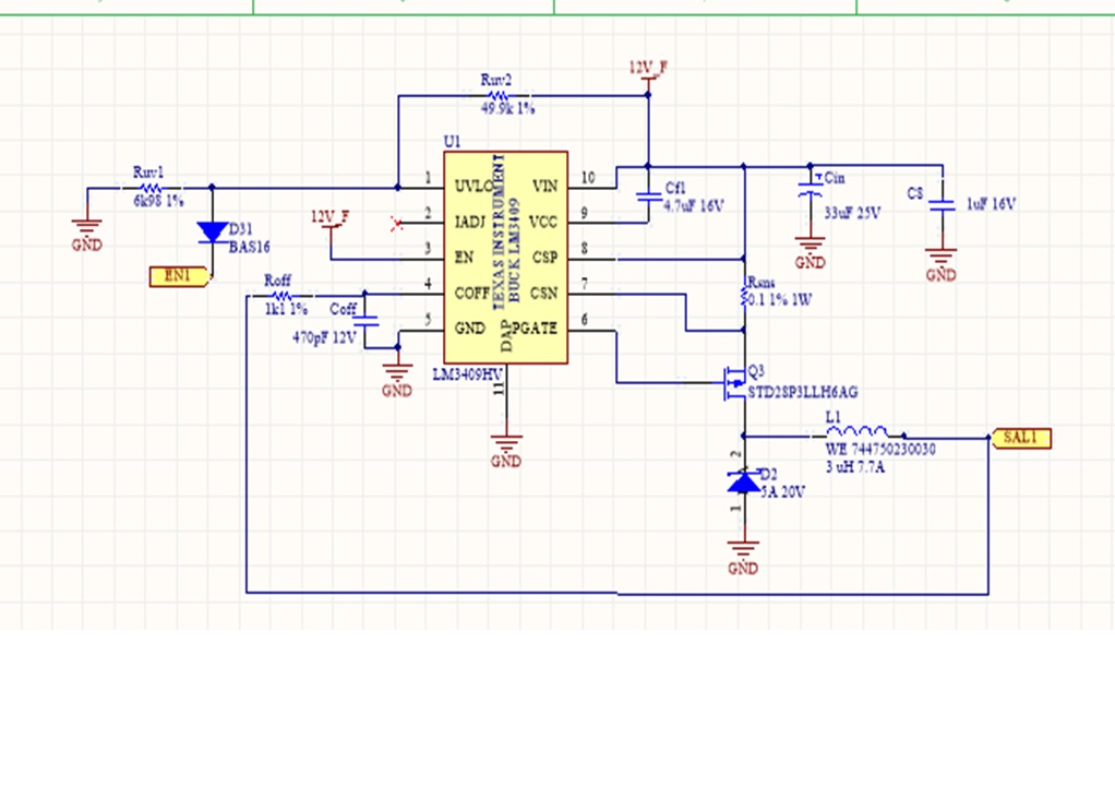
SAL1==> it has 2 rows of 4 leds each in paralell, each row 1 A, so SAL1 should conduct 2 A, at 11 V voltage

EN1 ==> it is a pulsed signal, duration of 800 us and about 20 FPS

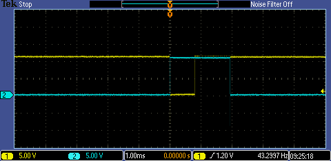
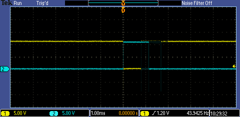
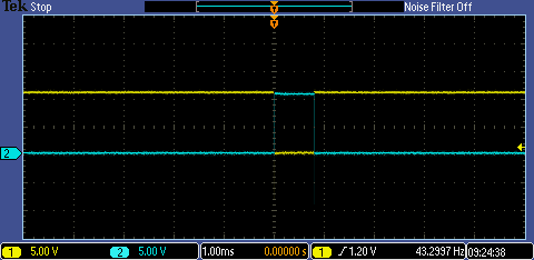
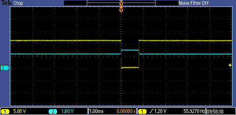
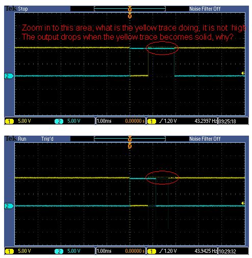
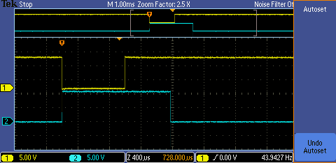
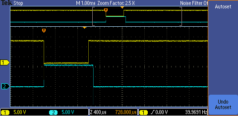
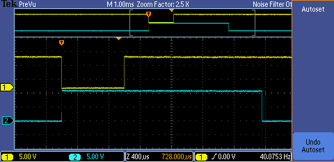
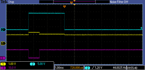
However, I have some unstabiity in the output time, which should follow EN1 (Second image is EN1, first image is a reverse signal previous to EN1 called pulse1, for practical reason I will show most of times pulse1):

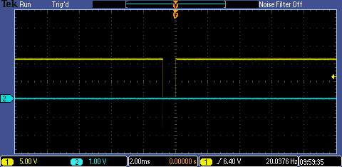
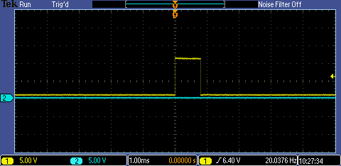
Signal is stable an clean. but when I probe sal1(blue), I have a signal that oscilate between 800 us to almost 2 ms attaced is shown some screenshots in the oscilloscope.

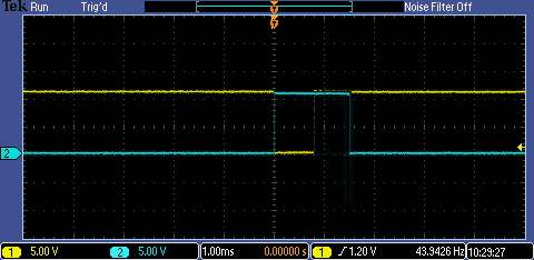
Honestly dont know what could happen. Maybe too much current?

Regards

  • Hello Ramiro,

    Is your command oscillating?  What is Vin doing during this time.  I assume that the yellow trace is the command per the first two pictures, one inverted one not.  Are the last three pictures in the same order, yellow is command and blue is output?  It seems the input voltage and LED voltage are almost the same, this may cause strange behavior.  Also, can you get a clearer picture of the oscillation?

    I will run some calculations on your design to see where it is operating.

    Best Regards,

  • Hello Ramiro,

    WIth Roff at 1.1 Kohm the off-time with 11V output is only 65 ns.  Depending on how much overhead voltage, or if there is any at all the switching frequency range can be very large.  I also get inductor di/dt of 0.237A.  This means the average output current will be 2.34A since the peak current threshold is 2.46A

    Have you looked at the switch node during this operation?  Is it even switching or is the MOSFET just turning on?

    Best Regards,

  • Hi Irwin,

    You are right about yellow trace, is the command signal.  and, despite the quality of the picture, is all the time 800 us wide. However, output blue trace change the wide: output is 1800, 1500 and 800 us (third, fourth and fifth picture ) depending just on the different moment my finger push the save buttom at the oscilloscope :(. It is oscillating all the time

    I will check the difference between Intput and output voltage and I will let you know, but assuming the output voltage, I guess that this could be only possible if the led string is giving higher voltage than 11 V at that current, so the only way to have a lower output voltage is reducing I. Is this correct? what should be a minimum voltage difference beetween input and output for proper operation?

    regards

  • Hi Irwin:

    Should I choose a lower value of Roff?

    Regarding average output, 2.34 maybe gets a Higher voltage than expected==>therefore maybe the output and input votage could be very similar. Correct?

    Last answer to your question==> the MOSFET seems it is turning on and off, as I said the output is switching but oscilating in the length of time pulse.

  • Hello Ramiro,

    Yes, I would make Roff a larger value, try 4.7 Kohm, that will drop the average to just below 2A at 1.954A calculated

    I don't understand the oscilloscope pictures.  I see the inverted command high and low however there is a portion that I cannot tell what it is doing.  During this time the output is either on or off (off in picture 5 and on in pictures 3 and 4), the two that are on line up with the portion of the yellow trace which cannot be seen in the picture.  I cannot tell if this is a command issue or something else.  Also, since this is the inverted signal perhaps the UVLO signal looks different during this portion of time?

    As for Vin being close to Vout, it can be, there may be a side affect that causes the average current to be higher because the inductor charging doens't look like just an 'L' charging but and 'RL'.  This is due to resistances in the output including the current sense resistor and the dynamic impedance of the LEDs since there is no output capacitor.

    The LM3409 will just turn on until it reaches peak current.  If the LED string voltage reaches Vin - IR losses it will not reach the peak current threshold and the MOSFET will just stay on.  This isn't damaging it just won't be regulating.

    I will need to see clear pictures of the actual UVLO pin and the output as well as the switch node.

    Best Regards,

  • HI Irwin

    Here you have some clear pictures (I hope). Yellow trace is EN1 inverted(it is actually a previous signal), starting always at 0, ending always at 800 us . Blue is output, which should follow EN1. As you can see bue trace it´s oscillating all the time while inverted EN1 is correct wide always

    On the ther hand , In the next picture you can see in blue UVLO, 

    I will try to change Roff to see if there is any difference

    Regards

  • Hello Ramiro,

    Move your scope trigger to the left and change the time base to get more of the waveform on the screen.  Also make sure the scope sweep is a single sweep otherwise you don't know what you are looking at.  Roff will most likely not change this behavior.

    Best Regards,

  • Hi Irwin:

    I attached some screenshot to see if get some light to your questions

    You can see both signal with an ofset, oscillating the time of the output.

    Yellow trace is 11.5Volts (I need to check why

    Blue trace (output) 11.0-11.1

    I have measure Vin and it is not 12 Volts, it is 11.1, so its a litle strange. I need to review Vin. this is the trace of Vin , in which Vin decays a little bit (blue in next picture):

    So this behaviour could be because Vin and Vout are quite the same?

    regards

  • Hello,

    Thank you for the clearer pictures.  If UVLO is being pulled below it's turn-off threshold it should turn-off so I would look at the UVLO pin of the LM3409.  Do you have a method to look at the output current?  You are looking at voltage which doesn't reflect what the LM3409 regulates.  Can you look at the switch node during these pulses if you don' t have a current probe?  This will tell you two things, if it is switching and if it is turning off when the UVLO goes low.

    What does the circuit look like that is driving EN1 (the UVLO pin)?

    As for low Vin, The LM3409 will just turn on the MOSFET until it reaches peak current trip.  If it doesn't reach it just stays on.  Looking at the switching node and LED current will show this.

    Best Regards,

  • Hi 

    The Mosfet is turning on and off, so its switching the current. I have not a current probe, but I can see the LED switching all the time, so current is being passing trhough.

    Hi have look at UVLO agains output, and maybe this clear what is happening. Yellow trace: UVLO. Blue trace: output, pink trace, enable signal. If you look at the pictures, UVLO is not  always turning off completly when the enable signal is off. 

    First picture: output follows the UVLO signal, which follows enable signal 

    First picture: UVLO dont follows enable signal. UVLO has 360 mV between low and high level, but now appears a not desired level of 120 mV before going tottall down, that allows the mosfet to be switched during some ms more (until UVLO goes down at low level)

    Dont know why

    regards

  • Hello Ramiro,

    What is the circuit driving the UVLO pin?  UVLO has a 22 uA hysteresis current source.  It appears there is significant impedance in the circuit pulling EN1 low.

    Best Regards,

  • Hello Ramiro,

    22 Kohm is not enough to pull the UVLO low.  There is a resistor divider for UVLO on your schematic.  You have a node with Ruv2, Ruv1, R3 and 22 uA of hysteresis current as well as a diode drop from D31.

    I calculated the voltage at that node assuming 0.5V drop on D31 and came up with 1.36V which is higher than UVLO shutdown threshold.  R3 needs to be quite a bit lower for this to work.  Seems like an NPN pulling to gnd would be better.

    Best Regards,

  • Thanks !

    Lowing R3 to 10k solved my problem. You are absolutly right.

    Best regards