This thread has been locked.

If you have a related question, please click the "Ask a related question" button in the top right corner. The newly created question will be automatically linked to this question.

LM5050-2: The necessity of the protection diode and input/output capacitance in case the external protection circuit exist

Part Number: LM5050-2

Hi team,

We are going to use LM5050-2 at typical 12V power supply and there is the external protection circuit(e-fuse) on the output side.

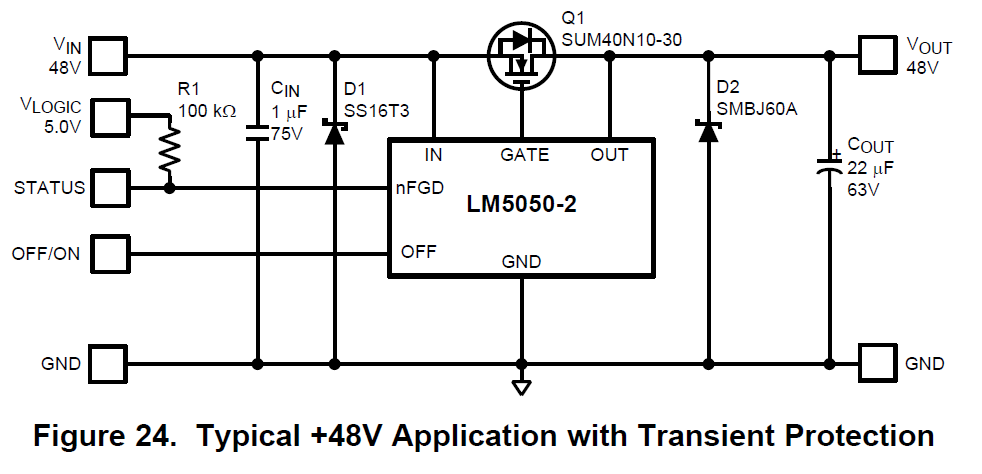
Is it possible that the protection diodes D1,D2 and the input/output capacitance Cin/Cout remove in below application circuit(Figure 24) ?    

(e-fuse:overvoltage,undervoltage, overcurent, inrushcurrent protection)

Is it dangerous? Would you let me know your concern ? 

Thanks

Best regards,

Akita

  • Hi

    The protection diodes and input/output capacitors are required during reverse current turn off and if that current is huge, we could see large transient spike that could damage the IC.

    Could you share the load current level?

    Please refer to the transient protection section in the datasheet for more detailed information.

    Regards,

    Kari.

  • Hi

    D1 is required to prevent IN pin from damage when IN pin voltage can go negative during reverse current turn off of MOSFET.

    However D2 protects over voltage at OUT pin and if OUT pin voltage does not exceed 75V, D2 may not be required.

    For example, when the eFuse or Hotswap circuit after LM5050-2 turns off, there will over voltage on OUT pin during eFuse turn off. Sufficient capacitance may be required to prevent overvoltage if TVS is not used.

    But minumum CIN and COUT is required, and the values of these can be decided current in the load.

    Transients protection requirements during an input supply short is detailed in page 13 of datasheet.


    Regards,

    Kari.

  • Hi Kari,

    Thank you for the reply and I'm sorry for the late response.

    >Could you share the load current level?

    About 10A at typical, and it never exceed 12.5A.

    Thanks to your explanation,  I'm starting to understand the necessity of CIN,COUT,D1,D2 even if there is efuse on the output side.

    I've read page 13 of datasheet and known the role of these parts. 

    But I would like to mizimize the board layout if possible.

    I understand importance of the output capacitor COUT.

    Is it possible to replace the COUT, a polar capacitor with a ceramic capacitor ?

    Thanks

    Best regards,

    Akita


  • HI Akita,

    For 12.5A design, D1 and COUT are minimum required.

    COUT can be ceramic capactior, no issues.

    Regards,

    Kari.

  • Hi Kari,

    I understand.

    Thank you for your cooperation.

    I'll close this thread.

    Thanks

    Best regards,

    Akita