Tool/software: WEBENCH® Design Tools
Hello,
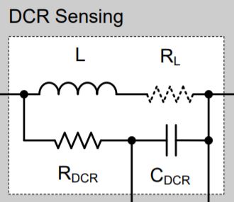
I'm trying to understand the DC current sensing of the TPS40090 steady state simulation. According to the reading material when RDCR and CDCR are selected in such a way that the RC time constant is equal to the ratio of inductance and series resistance of the inductor, the voltage across CDCR will be directly proportional to the inductor current (IL)
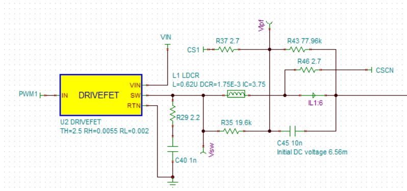
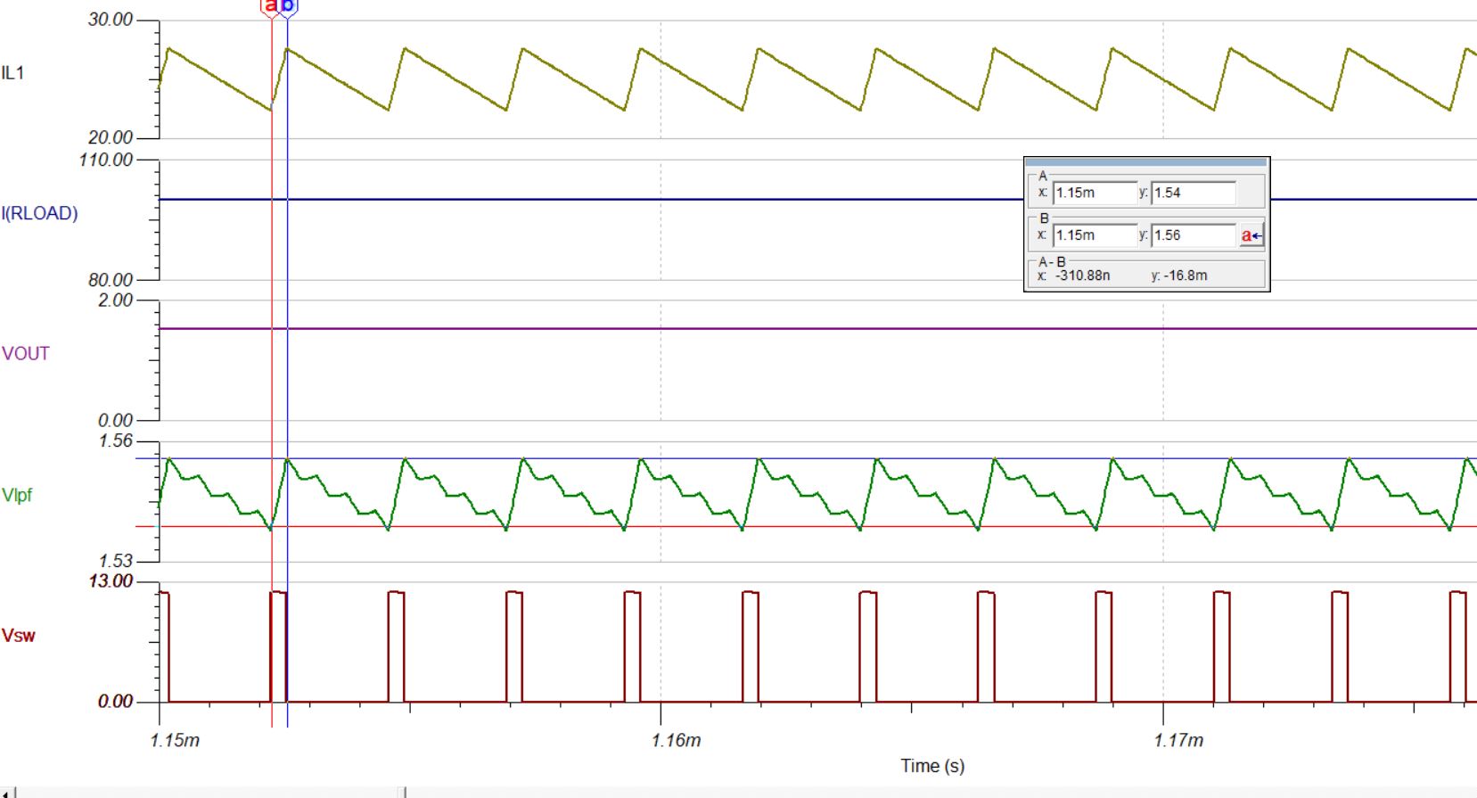
Next, i'm using the TINA TPS40090 steady state simulation file to understand this concept further (as shown below). But when i probe at Vlpf, the voltage across the C45 is around 1.56V (refer waveform below). Isn't it suppose to be 43.8mV in order for it to get 25A for each phase (using formula of Vdcr=Iload X RL)? Attached is the simulation file. I'm running transient from 0 to 5mS. Thanks