This thread has been locked.

If you have a related question, please click the "Ask a related question" button in the top right corner. The newly created question will be automatically linked to this question.

BQ77915: Chooseing transistors.

Part Number: BQ77915

Dear Community

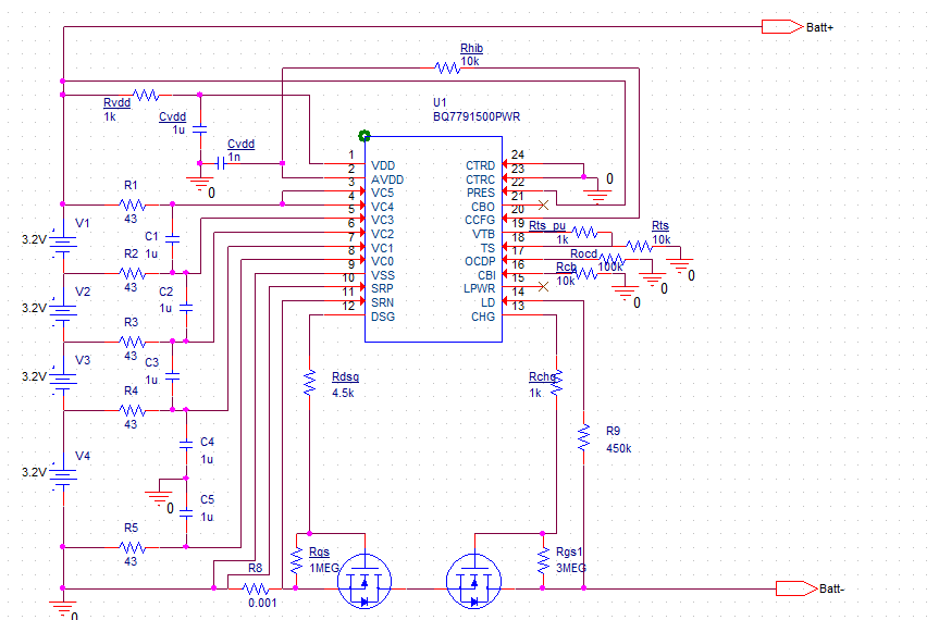
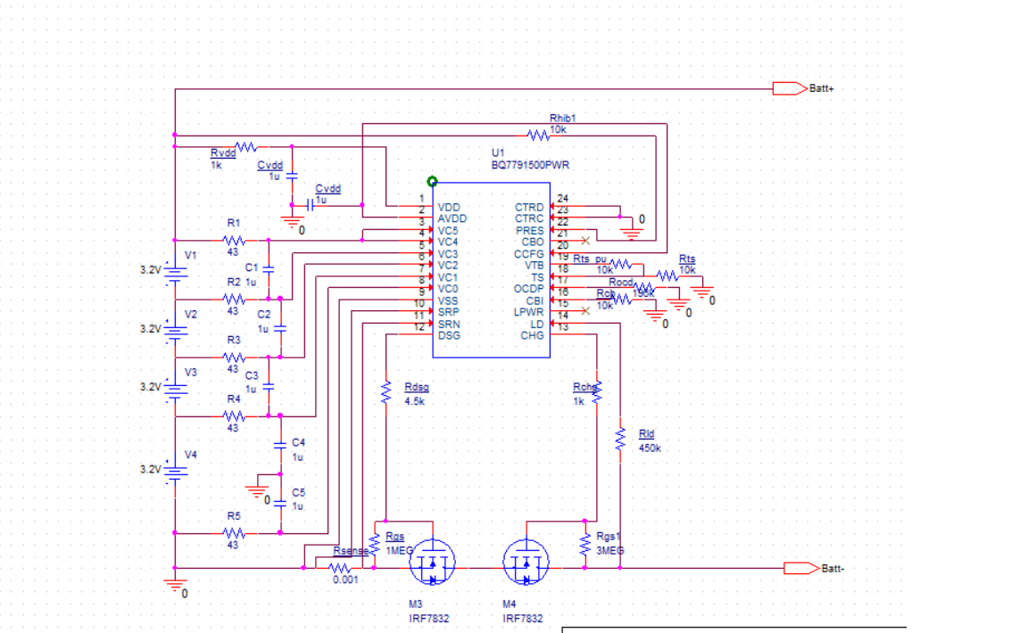
Hi! I am working on building schematics for my BMS which will be connected to 4*LFP batteries in series (total 12.8~14.4V/3A)

my output current is tageted to have 4~8Ah discharge rate but i am having trouble with choosing CHG and DSG transistor values.

I randomly chose some transistors for filling up the blank but i need help with finding proper FET and check if my schematic looks reasonable.

Can you guys help me with this? Thank you! 

  • Hi Hojung,

    I notice a few items in the schematic:

    • The AVDD cap shows 1nF, 1uF is recommended in the data sheet.
    • The data sheet largely leaves the PRES connection to the user.  In the schematic RHIB is used in the CFG pin path, it should likely be used to connect PRES to the battery, or connect to VDD which is already filtered.  The CFG pin is normally connected directly to AVDD when needed.
    • Rts_pu is shown as 1k, this is normally 10k.  You can adjust the value to adjust the temperature where the device trips at its ratio, but 1k seems extreme.

    For the FETs, your FET will likely be selected for thermal properties rather than current.  Many batteries are self contained with little heatsinking possible, in such a case you may want a low RDSON resistance so heating inside the battery is minimal.  You may want overcapacity in the FET to handle heat during protection switching.  If you have a good heatsink available you might use a lower cost FET with less margin.  You will normally want a FET with a +/- 20 V Vgs limit, and a Vds limit of perhaps 150 to 200% of your battery voltage depending on if you want the FET to suppress transients.  If you are designing a 14V max battery you might be selecting a 25 or 30 V FET.  So it is not the easy answer I would like to give, but there are many considerations and you will need to select based on what is most important for your design.

    Be sure to look at the section 10.1.1.2 in the data sheet for the CHG drive circuit.  With 14V you should be able to use the circuit you have drawn.  If DSG is off and PACK- is pulled to PACK+ with CHG low the FET should be safe, but consider if your pack will have transients which may require additional considerations.

  • Thank you for the reply!

    I fixed the resistor value based on schematic and i actually made an mistake on putting Rhib onto CFG path. 

    I chose to use SQ4282EY-T1_GE3 for DSG transistors but am seeing I need PMOS FET for CHG pin but cannot find the max -30v product. Would this be proper choice to operate this chip? Thank you!

  • Hi Hojung,

    Either the proposed FET or the one in the schematic should be fine, consider the heating.

    Normally a P-channel is only needed for CHG if the charger voltage will be very large.  You can use a higher voltage signal FET if desired.

    The risk to M4 is if you have DSG and CHG off with BATT- flying up to a high voltage, the gate of M4 could be stressed.

  • So as i am charging with 14.6V, Would connection without M4 works properly?

    Thank you!

  • Hi Hojung,

    Yes, without M4 it can charge through the body diode of M3 if it is off, but the BQ77915 will detect a modest charge current and turn on M3.  However M4 is often considered an important feature in the BMS since it prevents charge current when the BQ77915 determines the cell voltages are too high. Of course your system may have other features to prevent overcharge of the battery.