A related question is a question created from another question. When the related question is created, it will be automatically linked to the original question.
If you have a related question, please click the "Ask a related question" button in the top right corner. The newly created question will be automatically linked to this question.
UCC28950: ucc28950 could not find examples for parallel use
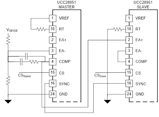
This system uses the basic idea in the diagram below.
The arrangement above can be extended to multiple slaves but all the slaves will run at 90 degrees from the master. This is correct for one slave but for more than one slave the phases of the slave devices need to be equally spaced for optimum interleaving. This is described in the app note below - which is where I think you got the TLC555 and 4015 device references from.
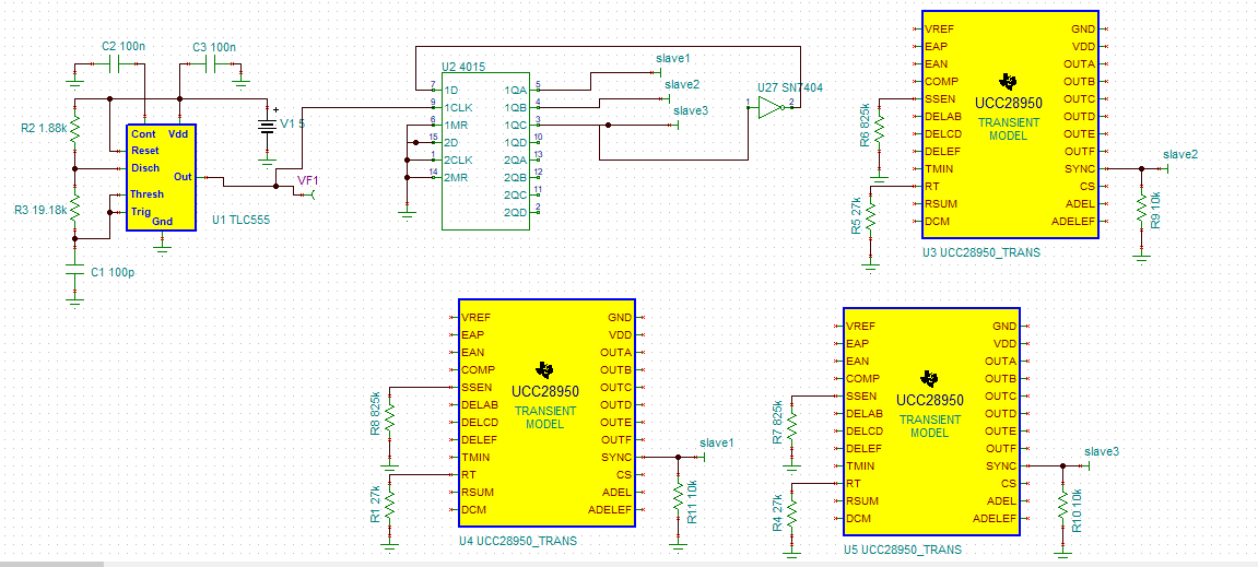
I'm trying to build the structure described in the slua609 document, I'm trying to build the structure containing tlc555 and 4015, but I can't find any sample schema.
4015 integrated outputs do I need to connect directly to the sync pin?
if I did an example design can we talk on accuracy?
The SYNC input to the UCC28950 requires a 0/5V or 0/3.3V signal. It depends on how you use the 4015 and you may need to use an attenuator if its output signal amplitude is larger than that but the 4015 output can go directly to the SYNC pin given that the amplitude is correct.
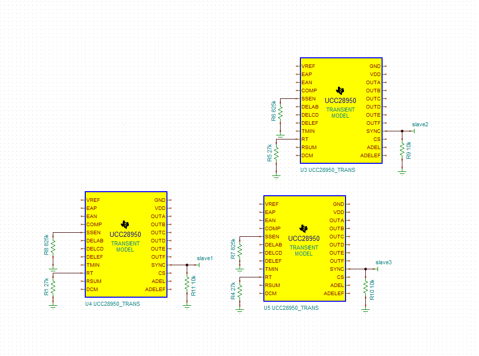
The UCC28950 must be configured as a SLAVE device, RT connected to GND.
I'd suggest you use the UCC28951 instead of the UCC28950. The UCC28951 device is an enhanced version of the UCC28950. It is a fully compatible drop-in replacement for the UCC28950. Refer to application note SLUA853 at http://www.ti.com/lit/an/slua853/slua853.pdf for more details. The UCC28951 is typically the better choice, especially for applications where the system may have to operate simultaneously at a duty cycle> 90% and current limit.
I can check your design for you if you wish - that's not a problem
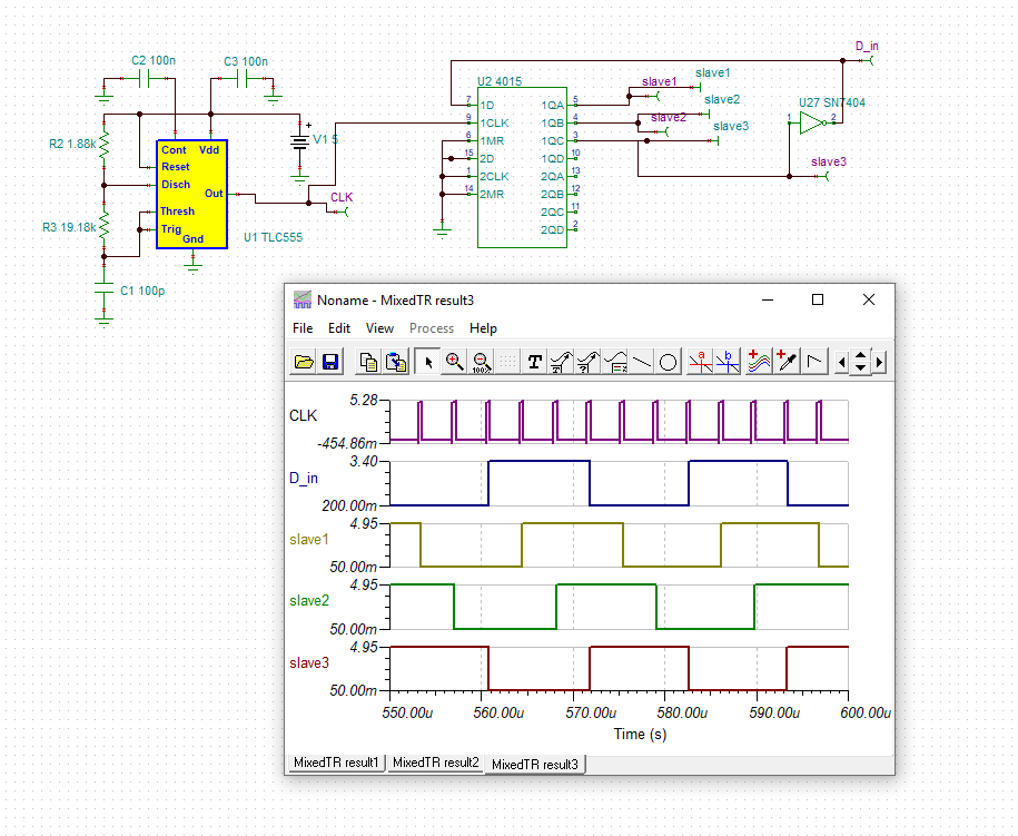
Your circuit should work fine - I hacked your file to remove the UCC28950 devices (makes the sim run much faster) and the output signals to the slaves are correct. I've also attached the modified tina file.
The resistors above are correct, You will need a capacitor at the SS/EN pin if you want the soft start function to operate correctly.
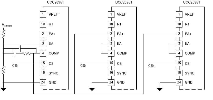
That is all you need for synchronisation. You may also want to have the power stages share the load current and for that you will need a circuit like that below. The error amplifier of the controller on the left sets a current demand which is shared between the other two controllers. This method can be extended to more stages. This method was used in the PMP6712 reference design at http://www.ti.com/tool/PMP6712
They are different and both will work well. However, like many things it depends on what you want the system to do - here are the main comparisions / tradeoffs.
Transient response will always be slow with the UCC29002 because its control loop bandwidth must be about a decade slower than that of the modules it is controlling.
Load share accuracy can be better with the UCC29002 because it has been designed specifically with highly accurate load sharing in mind.
The UCC28951 load sharing has a master controller and the other modules are slaves.
The UCC29002 is a 'democratic' system because the master controller is chosen automatically (it will be the one attached to the power stage with the highest output voltage). This means that a true N+1 redundant system can be built. If the Master UCC28951 fails in the system shown above then the whole system will stop.
If you are happy with these tradeoffs then the UCC29002 is a good solution.