This thread has been locked.

If you have a related question, please click the "Ask a related question" button in the top right corner. The newly created question will be automatically linked to this question.

BQ77915: OV detection when new battery connection

Part Number: BQ77915
Other Parts Discussed in Thread: TEST2

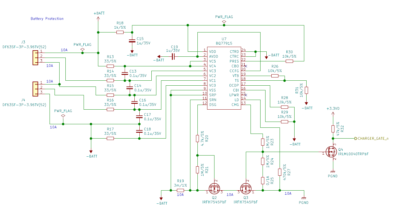
I designed 4cells BMS with BQ77915 and tested. I'd like to know how CHG pin of BQ77915 works when new battery is connected.

Test1) Connect fully charged battery (SOC 95%, 16.6V(4.15V/cell))

-> CHG pin is low. When starting to discharge, CHG pin is high. After stopping to discharge, CHG pin is low.

Test2) Connect NOT fully charged battery (SOC 50%, 15.5V(3.875V/cell))

-> CHG pin is high. When starting to discharge, CHG pin is high. After stopping to discharge, CHG pin keeps high.

Test3) After Test2, Charge the battery (with BMS)

-> CHG pin keeps high. When starting to discharge, CHG pin is high. After stopping to discharge, CHG pin is high. The battery voltage is about 16.6V. (4.15V/cell)

I think the results of Test2 and 3 are normal, but I could not understand why the BMS works as Test 1.

Fully charged battery should not connect ? If connected, the battery should be discharged ? Or is there something wrong in this circuit ?

  • Hi Fuji,

    See the BQ77915 data sheet overvoltage section https://www.ti.com/document-viewer/BQ77915/datasheet/fault-operation-slusbz71909#SLUSBZ71909.  "The device assumes an OV fault after reset..."  So if you are at a high enough voltage to be in the OV hysteresis region, the part is in OV mode when it wakes up and will have the CHG output off as you indicate.  When discharge current flows the body diode protection system will turn on CHG, but when current stops it CHG will turn off again until the voltage is below the UV hysteresis level.

    So test 1 is normal for the  BQ77915.  It may not be what was expected.  It is good in that it prevents a user from topping off a full battery, some hysteresis is required before charging more.

  • Thank you for your kindly support.

    In my understanding, if the voltage of the battery is higher than 4.0V/cell (threshold(4.2) - hysteresis(0.2) = 4.0), OV is detected. So the Test1 is normal.

    In the factory of our product, I'm considering that we have to follow the procedure like this. If you know some idea, could you advise?

    1. Charge or discharge the battery to middle level. (lower than 4.0V/cell)
    2. Connect the battery to the circuit board (BQ77915).
    3. Charge the battery to full level.

    Additional question.
    If I'd like to disable DSG/CHG-off by some protections and use only cell-balancing, can I remove CHG FET and DSG FET ?

  • Hi Fuji,

    The BQ77915 assumes OV if it sees the cells in the OV hysteresis region when it wakes from hibernate mode. So yes, test1 is normal for the part.

    We understand cells and batteries are typically shipped and assembled with partial charge.  In this case the BQ77915 would not be in OV after wake.  If your factory situation has cells fully charged at assembly discharging to below the OV hysteresis level would be needed to reach the normal state.  Your sequence should work.

    The part does not need CHG or DSG connected, they are outputs and can be left open.  While LD has a pull down in certain modes it is an input and should be tied to VSS.  The BQ77915 does need to see current for balancing.