This thread has been locked.

If you have a related question, please click the "Ask a related question" button in the top right corner. The newly created question will be automatically linked to this question.

BQ76940: Zener and pull down significance in low side mosfet driver circuitry of Bq76940 datasheet

Part Number: BQ76940

Hi,

Please share significance of pull down resistor and zener across it in charge side mosfet, because wanted to know when to increase resistor value beyond 1mega Ohm   ? What happens when we change value to 25mega ohms , some application works well and some do not. SO please share why it i s1 mega ohm only and when to decrease it or when to increase it ?

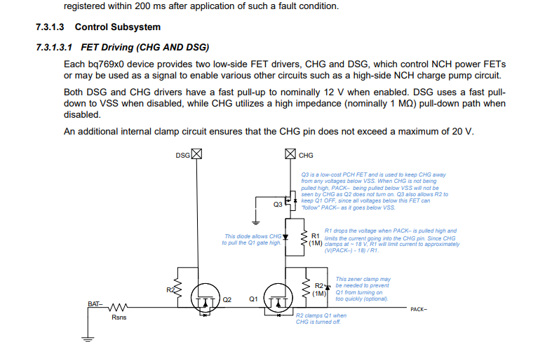
Sharing its image for quick reference:-

  • Hi Rohit,

    The zener has 2 purposes. 

    First suppose the battery is at a low voltage, too hot to charge, and a charger is applied which is more than the max Vgs of Q1 greater than the battery voltage.  In this case the max Vgs limit of the FET would be exceeded and the FET might be damaged when CHG starts to go high when the battery cools without the zener.  It would be a race between the FET turn on and Vgs rise.  FET experts have recommended the zener.

    Second, suppose you have a 50V battery which experiences a fault and turns off with the load pulling PACK- to PACK+.   The pack voltage will distribute across R2, R1, and RCHG_OFF internal to the IC.  The CHG pin is clamped at 18V nominal, so quiescent the other 32 V would distribute across R1 and R2, if they are matched, 16V on each.  During an inductive transient from switching current, the voltage could be higher. A back to back zener could be used to limit the negative Vgs, but that would take another component.  Allowing the Vf of the single zener diode to force the voltage across R1 allows fewer components. 

    As CHG starts to turn off, the gate of Q1 is  pulled down by R2 and R1.  Once Q3 turns off only R2 pulls down the gate and completes turn off of Q1.  A larger R2 reduces quiescent current when on but slows turn off.  A smaller R2 turns off Q1 faster but requires higher quiescent current. When you need faster turn off you might consider an isolated gate driver (and isolated power supply for it), or a clamp transistor on the gate whether controlled passively or with a driver circuit. You have tradeoffs with current, complexity and components.