This thread has been locked.

If you have a related question, please click the "Ask a related question" button in the top right corner. The newly created question will be automatically linked to this question.

DCR011205: DCR011205 (and DCR011203) overshoot

Part Number: DCR011205
Other Parts Discussed in Thread: DCR011203

I am using several DCR01 regulators in one of my designs. There are two sets of 3, one DCR011203 and two DCR011205s. Both sets have completely independent loads. They have sync pins tied together within a set, but not between sets. All regulators use recommended capacitance and resistance values.

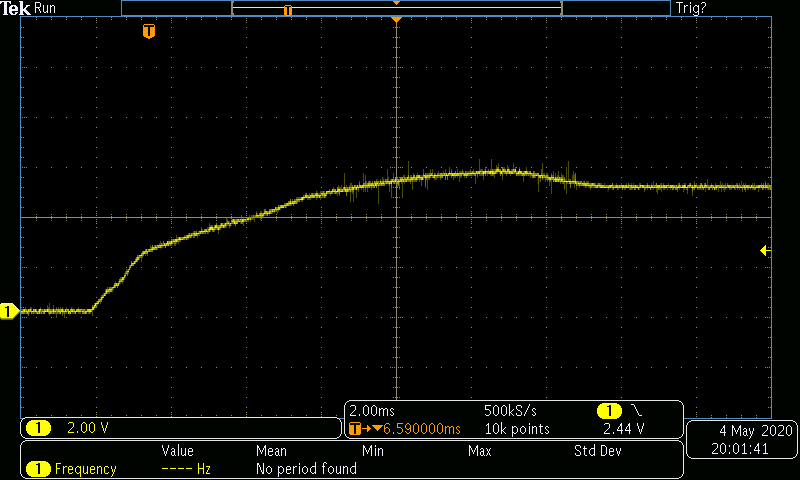
I'm noticing significant overshoot from all regulators, generally ~1V. A screen capture is attached for reference. This is unacceptable for my design, as many of the 5V components have an absolute max of 6V, and some of the 3.3V components have an absolute max of 4V. Are there any established methods for soft starting this regulator? It doesn't have an SS pin, so this isn't going to be as simple as adding or changing a capacitor.

I'm not certain because of the hybrid nature of this part, but since the output stage is an LDO is the method highlighted in the attached PDF a usable one here? Is something else preferred?

 1616.Soft-Start Circuits for LDO Linear Regulators_slyt096[1].pdf

  • As an alternative to that soft start method, could it be that I just need to put the enable on a divider? This reference (attached) seems to indicate that as a method of minimizing LDO overshoot. Note that the enable threshold for this part is only 2V, input voltage is nominally 12V, and outputs are 5V and 3.3V.

    It also cautions against overcurrent, but I don't believe my design is in an overcurrent situation for the benchtop supply or for these 1W power suppliessbva060.pdf.

  • Hi Francesco,

    You did your research well on attempting to solve this issue. I would agree with what you stated. We recommend you take the approach of implementing an enable resistor divider onto your application (method #2 on Application Report you provided).

    Approach: Allow Vin to reach regulation before the LDO is enabled.

    Regards,
    Alejandro

  • Thanks, I implemented the divider and it does seem to have resolved the overshoot issue.

    One thing I'm seeing that I don't understand, though - the 5V supplies are starting up with a very clean and continuous rising edge, but the 3.3V supply is showing a pause at 2V for several milliseconds, and then continues at a more gradual slope. Do you have any idea why that might be? The overshoot is still gone, but I'd like to have full understanding of what I'm seeing.

  • I think I might have a clue, and it's related to the load, but since the only components on the load of this regulator are also TI parts, I'll run it by you here:

    The components are ISO724x isolators, and associated passives. They have their enables pulled up to the 3.3V rail, but the threshold of the enable is 2V. This 2V level is potentially relevant here because that's when the regulator starts slowing down.

    However, one of the 5V regulators is also tied to another side of these isolators, and doesn't show the same lag at 2V. So it's possible I'm on the wrong track, or still missing something.

  • It seems you beat me on answering a question I had in mind "What is connected at the load?". After reading a few lines from your response, I had the same conclusion as you have: The enable threshold of load is causing a slow down. The load beings to demand for current when it reaches 2V and the supply is trying to catch up.

    You mentioned that a 5-V regulator is also tied to "another side" of the isolators? Can you provide a little more info on that? Are the input requirements identical for both inputs?

  • There are two ISO7240 chips and one ISO7242. They all take a VCC for either side of the isolation. One side is supplied by 3.3V, the other by 5V. The 5V side also has additional loads, but since it's starting up fine I'm discounting those. The 3.3V side powers only its side of these isolators (other 3.3V loads on the board use yet another regulator, which also starts without issue). If you have a datasheet handy, 3.3V is always VCC1.

    The vast majority of the IO on the 3.3V side (10 of 12) are inputs. The remaining 2 are outputs. The reverse is true for the 5V side. Both inputs and outputs for the 3.3V side are connected either to microcontroller GPIO or to 10k resistors that pull inputs to an initial state. The outputs are where I would expect a large load current to be (if anywhere), but they're just going to microcontroller high impedance inputs. I know they're configured correctly because I've used them.

    For the ISO7240 chips, the enable is on the 5V side only, presumably because all outputs are on the 5V side for those parts. Since the 5V regulators are starting up earlier and faster, the 3.3V side is coming up while the component is already enabled on the 5V side. I'm not sure whether or not that is factoring into this, because the two sides are supposed to be independently powered.

    Slight update: I tried putting a divider on the enable for the 3.3V side of the ISO7242, but no change in the startup of the regulator. Looks like whatever is happening is independent of those outputs.

  • Francesco,
    I believe there might be differences in the internal threshold for each device. I tried looking for internal component information to maybe find differences, but, unfortunately since these are +15 year old parts, gathering info was difficult.