This thread has been locked.

If you have a related question, please click the "Ask a related question" button in the top right corner. The newly created question will be automatically linked to this question.

BQ77915EVM-014: Cell balancing in BQ77915

Part Number: BQ77915EVM-014
Other Parts Discussed in Thread: BQ76920

Dear Forum Members,

I have a BQ77915EVM card and try to test it in 3 cell configuration with real Li-ion cells.

I successfully tested the Discharge Overcurrent (OCD), Short (SCD), Undervoltage (UV) protections with oscilloscope (CH1: current sensing resistor signal, CH2: DFET Gate, with Single Mode) and

Normal/hibernating modes current consumptions (with DMM, they are fullfil the specifications, note, very attractive values).

Now I am checking balance operation but I met promblems: the balance procedure started but after expering certain amount of time it has stopped, thus the cells remained in unbalanced state.

I used mult-channel analog signal recorder for this test. I made two test: one did utilize only minor initial unbalanced condition, second used larger (allowing to raise OV event-> CFET turned off).

Charger setup. CCCV by PSU: 1A, 12,3V (3*4,1V, because '77915-00 variant has OVD=4,200V, Vfc=4,100V). Jumper in CBI state on EVM.

Somebody could suggest idea why stopped the balancing? Unfortunately the datasheet does not detail the stop conddition neither Vcbth nor Vcbtl (abs) levels, only a 100mV hysteresis mentioned. From my experiments, it seems balance starts at 4,1V (pls see ath pictures).

Thanks in advance for the comments!

Joseph

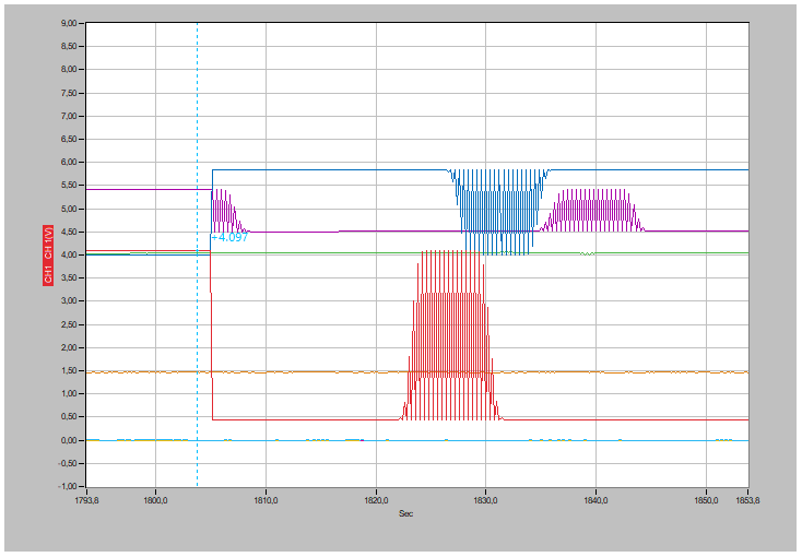
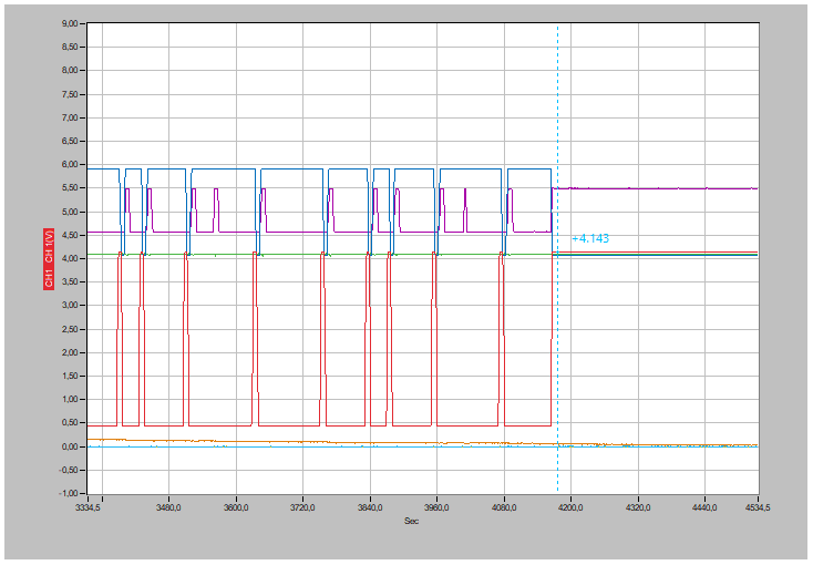
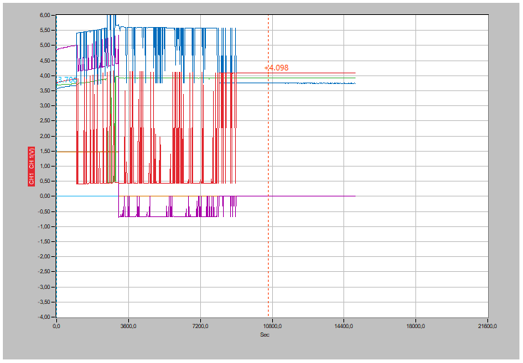
Graphs: CH1 RED: Lowe cell, CH2 BLUE: Middle cell, CH3 GREEN: top cell, CH4 PURPLE: CFET Gate, CH5 Orange: signal on current sensing element. Note: channels 1-3 are connected to

RINs lower pad (IC VCx pins) thus when balance ON the measured voltage value corrupted...but it is not so important, I wanted to see how switching. When balance OFF: measured voltage values became again correct for the analyzer.

Minor initial unbalance, sample rate: 200msec (max speed). Before turing ON charger, cells are: 3,763, 3,703, 3,712V

Magnify : it is corresponding to datasheet which states the BQ applies 200ms balance-test interval

End: by the end cells: 4,143, 4,069, 4,093V

with Larger initial unbalance: cells: 3,706, 3,508, 3,620 before turning ON charger

It can be seen, CFET also turns OFF (top cell reached the OVD level)

By end of procedure: 4,098, 3,748, 3,921V thus highly unbalanced

  • Hi Joseph,

    Thanks for providing excellent details and waveforms to describe your issue! The cell balancing feature can be very confusing since it is a fixed hardware state machine algorithm.

    The key parameters that are fixed based on the device number (see Section 6 Device Comparison Table in the datasheet) are VSTART, VHYST, and VSTEP. For the BQ7791500 which is used on the EVM, these are set to 3.8V, 100mV, and 100 mV.

    This video may help explain why you do not see the balancing turn on until the cell voltages reach 4.1V. It may be that you never have cells that are below VCBTH and VCBTL at the same time. Once the cell voltages cross VFC, then the balancing behavior changes and all cells above VFC balance. Balancing will stop once the charge current falls below the current state comparator hysteresis. The behavior changes again when a cell has gone above VOV. 

    https://www.youtube.com/watch?v=wewL0oJRBNM Youtube

    https://training.ti.com/how-cell-balancing-feature-works-bq77915  ti.com

    Best regards,

    Matt

  • Hi Matt,

    thank you vm for the explanation and the training material. No, I start to understand how  it Works.

    I try to summarize, I hope correctly:

    1. The balance thresholds are not fixed but increaed by VSTEP (100mV) when all cells above the Vcbtl level.

    If I understand correctly, the algorithm requires Vstart crossing which does fix the initial balance levels: Vcbtl=Vstart=3,8V and Vcbth=Vcbtl+Vstep=3,9V.

    2. Balance Termination

    charge current (>125mA) shall be flown otherwise balance is OFF (that's why balance switch OFF in may app because Icgh decreased by the CCCV charge method)

    3. 1st mode balance (after crossing Vstart=3,8V)

    From training material: "When the cells are separated enough so that one or more cells is below the lower cell balance threshold and one or more cells is above the upper threshold, the cells above the upper threshold will balance."

    In other words, balance Will not active (or stpped if it was active once) despite least one cell over the Vcbth level if no least one cell below the Vcbtl lvel (no enough difference).

    In my test, - after turning on charger- initial cell voltages were: 3,799V, 3,732V, 3,751V :balance did not start until cell#1 reached 4,1V (this is the other behaviour of the balancing as You mentioned). No (normal) balance was estabilsh because cell difference did not exceed Vset=100mV.

    4. Exceeding the Vfc full charge 4,1V level ( 2nd mode): for balancing not needed that least one cell shall be below Vcbtl. In this case balance Will be ON until charge current remains sufficient (state comparator still on)

    5. 3rd mode: overvoltage. Above Vfc, if cell voltage reach the Vov (4,2V) despite its balance in ON, the CFET Will be OFF (protection!) but balance still is ON and cell vill be dicharged to Vfc level (or overvolatge hyst) when balance Will be turned OFF.

    Remaining questions:

    1. What happens if initial cell voltage(s) are already above Vstart- no crossing-, say 3,9V, 3,7V, 3,75V,  when Ichg starts (state comaprator signalling)?

    How Will this influence further operation?

    2. Whether is this method able to accurately balance cell say within 10mV?

    3. Is there any thumb of rule to choose the Icb/Ichg ratio for optimum solution?

    Regards,

    Joseph

  • Hi Joseph, 

    Your summary looks correct to me - I think you have the right understanding. 

    For the remaining questions:

    1. What happens if initial cell voltage(s) are already above Vstart- no crossing-, say 3,9V, 3,7V, 3,75V,  when Ichg starts (state comaprator signalling)?

    How Will this influence further operation?  My understanding is that it should start balancing in this condition. Unfortunately we are working at home so I don't have an EVM to verify this.

    2. Whether is this method able to accurately balance cell say within 10mV? No, this accuracy will not be possible with this type of algorithm. You can achieve this accuracy with a device like the BQ76920. The BQ76920 is a battery monitor that works with an MCU - the MCU decides when to turn balancing on and off for each cell and can decide based on the measured voltages. It is a much more flexible solution but requires the user to develop their own code.

    3. Is there any thumb of rule to choose the Icb/Ichg ratio for optimum solution? That's a good question. I don't know of a simple rule. With faster charge, there is less time to balance so the balancing current may need to be higher. However, this device only balances a cell until it is below the upper threshold. There are different device numbers in the datasheet Device Comparison table and some of these have a smaller VStep (50mV) which may help improve accuracy.


    Best regards,

    Matt

  • Hi Matt,

    thanks for the help, I may turn toward BQ76920 or 925 if higher balance accuracy required conjunction with an MSP430.

    I would have some question about '430 too:

    - for functional safety Systems (where -for example CFET/DFET shall be controled by the MCU -> 76925) which MCU series preferred: maybe 430G2xxxx?

    - which MSP430 seriesis not recommended for such (battery management/charging) applications?

     -what is the difference between G and F series?

    - which MSP430 pheripherals MUST be used (or strongly preferred) for such application (SVS, Brown-out reset, Watchdog, RC ring oscillator instead of (fragile) quartz?) Software: continous RAM/FLASH ROM CRC/Hamming check etc?

    - which MSP430 development tool (assembler, compiler) is approved to generate safety code (no bugs etc)?

    - what is about device errata? Does it mean beyond the reported bugs certainly no other bugs?

     -which clock signal is fail-safe (accidental stopping is excluded by the design), whether the internal RC ring type (DCO)?

    - How does the MSP430 immune against to EMI? What size is the technology node for varios 430 series?

    -Is there any reliability information (MTTF)?

    I have never used the 430 in a mass produced equipment only in uniqie instuments.

    Best regards,

    Joseph

  • Hi Joseph,

    Sorry, I am not an expert on the MSP430 so I am not able to answer your questions. If you create a new E2E post with these questions, it will be assigned to an expert from the MSP430 product line.

    Best regards,

    Matt

  • Hi Matt, no problem, I am testing the 77915 and may link to msp430 forum if really needed.

    I think we can close this thread since momentary I do not have more questions.

    Best regards,

    Joseph