A related question is a question created from another question. When the related question is created, it will be automatically linked to the original question.
If you have a related question, please click the "Ask a related question" button in the top right corner. The newly created question will be automatically linked to this question.
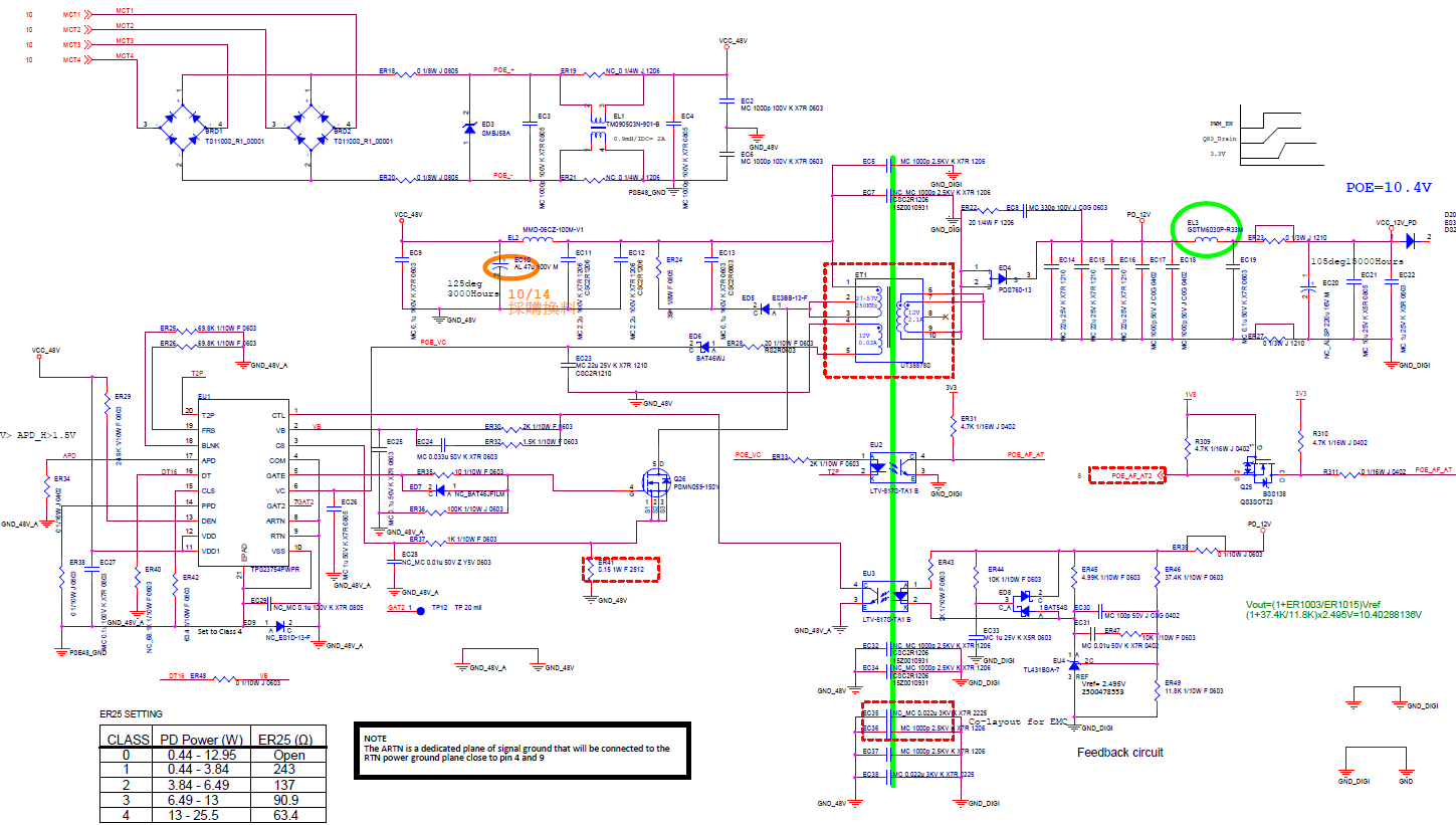
This design is a diode rectified flyback, it does not have the output inductor nor any electrolytic caps on the output. It also has a smaller input bulk capacitance. You could alter the design to be 10V.
Otherwise the components to look at are the inductor, the FET, the diodes and the transformer. The key with the diodes is the reverse recovery time and the power levels.
The key with the FET is ensuring the VDS voltage rating and current rating is high enough (usually 150V / 3A).
I would strongly advise NOT changing the transformer since so much of the DCDC is based on the transformer. However, people do it and it probably will have a noticeable cost difference.
If this post answers your question, please indicate so by marking this thread as resolved. Thank you.
we are also using PMP11254 as the basis for a low cost TPS23751 design. We have also changed the transformer against LinkCom LDT8202-51R.
Question: What is the allowable input voltage range for adapter supply? PMP11254 is rather limited form 41 to 57VDC. We would want to get to 24 to 57VDC.
Per the schematic label on adapter input J5, it can be seen the input voltage range is 41V-57V.
A class 4, 12V output design with adataper voltage 21V-57V is the PM8812.
You can find a full list of our publicly available reference designs on the site:
And you can filter these results.
Lastly, since this was a different question than the original question and a different project, please create a new thread on E2E next time. This helps us keep questions and answers clearly identifiable and searchable.
If this post answers your question, please indicate so by marking this thread as resolved. Thank you.