This thread has been locked.

If you have a related question, please click the "Ask a related question" button in the top right corner. The newly created question will be automatically linked to this question.

TPS735-Q1: Output current could be 1.9A?

Part Number: TPS735-Q1
Other Parts Discussed in Thread: TPS735,

Hi Team,

May I ask whether this SCH is ok? I found TPS735 connection is quite simple in datasheet...But customer add some bead/cap in their SCH...

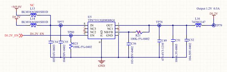
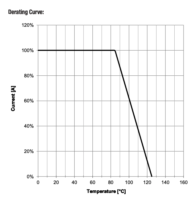
And it seems that TPS735 could output max 1.9A. In which situation, could it offer 1.9A output current?

Thanks!

  • Hi Amelie,

    The ferrite beads are OK. As long as the minimum capacitance at COUT is present, the LDO will be stable. The problem I see with the schematic is R21. R21 and C56 setup a low pass filter which will likely result in the regulator oscillating. What is the reason for this RC filter? Normally if they want to regulate to 1.2V you simply short FB to VOUT

    The output current limit shows where the current limit could engage. Meaning in the extremes it could be as low as 800mA or up to 1900mA. This current limit is present to protect the LDO and not the load. The LDO has a second tier of protection which is the thermal shutdown. if there is a short at the load, the voltage across the LDO will increase and the (VIN-VOUT)*ISHORT power dissipation will increase. This increased power dissipation will result in thermal shutdown.

    I hope this helps.

  • Hi John,

    Thanks for your quickly and professional answer.

    Customer is also a little confused about current limit in datasheet. When it is in a fault state, it will output a specific current value.

    What is this current value? Is it directly output to the load?

  • Hi Amelie,

    你太客氣!

    The current limit is a secondary and slower regulation loop than the voltage regulation. This is because the primary goal of the LDO is to regulate the voltage. Because the current limit loop is slower, where it trips is not a precisely tuned threshold This is why the datasheet shows a wide range.

    Also, another challenge in practically testing the current limit in the application is that thermal shutdown might kick in. This is a function of the PCB ambient temp and the voltage drop across the LDO. Meaning if VIN is 5V and VOUT is 1.2V, the voltage drop is 3.8V and if ILOAD is 500mA, the power dissipation across the LDO is 1.9W. In the DRB (SON) package the TJA is 52.2C/W so the thermal rise above the PCB ambient would be ~99.18C. If the PCB is at 25C, this is the maximum recommended operating temperature (25+99.18=124.18), If the PCB ambient is 50C, you may see thermal shutdown well before the thermal limit. 

    Just to make sure this is clear the die temperature TJ can be predicted by TJ=TA+(VIN-VOUT)*ILOAD*TJA

    When hitting thermal shutdown the output will be turning on and off. If measured with a DMM (which averages the voltage) you may see a much lower voltage than expected. If you use an oscilloscope, you would see the output turning on and off. 

    Sorry for the long answer, I hope this clarifies your question.

  • HI John,

    When I talked again with customer by phone, I figured out why he is so concerned about current limitation.

    They use TPS735-Q1 to convert 3.3V to 1.2V and the load is just FPD-Link DS90UB948.

    TPS735-Q1 max current is 500mA and the load FPD-Link max current is 230mA.

    They has SOP the head unit project,however, found one of the head unit machine failed.

    The output of TPS735 is only 0.5V, not 1.2V. The problem is on the bead (L16), the ferrite bead is damaged and the resister became large which may output voltage is 0.5V.

    When customer consult the  bead supplier, the bead supplier said the bead rated current is 500mA, if the current is higher than 500mA, this bead will be damaged for sure. So it is because LDO's current is higher than 500mA without current limit...

    To be honest, I don't think customer need to add bead in the output. May I ask whether there is risk (EMC...) if not adding  L16 bead?

     Have you ever heard about the similar issue? Output voltage is abnormal because bead is damaged. How could we give some advice?

    Thanks!

  • Hi Amelie,

    I found the datasheet for the ferrite and it has a DC resistance of 0.32Ohm. So at 230mA, there could be ~73mV dropped across the bead. The bead itself is only rated to 85C. at 125C, the datasheet clearly shows it can support no current. 

    If the bead is damaged, then its properties change and it could become more resistive. Can they either remove the bead or switch to one rated for a higher temp/current?

    Whether or not the bead is needed is really up to the application. It is quite common to use ferrite beads as shown in RF applications as they will help to block noise frequencies >100MHz. 

    I hope this helps.