This thread has been locked.

If you have a related question, please click the "Ask a related question" button in the top right corner. The newly created question will be automatically linked to this question.

ULN2803A: 91W faulty batch ?

Part Number: ULN2803A

Hello,

We use the ULN2803A as a signal switch and I am wondering if there is not a problem with a particular lot.

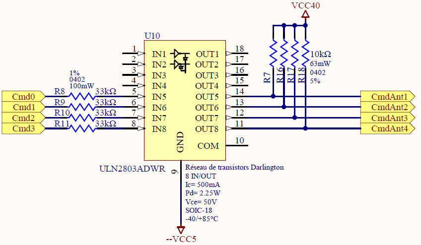
The inputs of the component are controlled by a basic microcontroller and the outputs are switched between two voltage levels (a low level connected to GND pin, and a high level 40V connected to pull-up resistors on each outputs).

We have been using this component for years and we are facing now the following issue : After several minutes, the 40V levels decrease on the ULN2803A outputs and lead the board to reset after a current rise which comes with the 40V decreasing.

This problem has occured only with some units of the following batch numbers (I guess it is the batch numbers):

91W71NB, 91WK28B and 91WDKDB

I can see this reference on the chip, before "ULN2803A G4".

The problem has never occured with the followings lots :

82ZE4T4, 82ZD6V4 and 78WK6N8

Is it possible that the 91W batch is defective ?

Thank you,

Thomas

  • Hi Thomas,

    I will look into these batch numbers and will get back to you when I get some feedback. In the mean time, would you happen to know if anything else has changed in the system that could affect the ULN2803A?

    Best regards,

    Andy Robles

  • Hi Andy,

    Thank you. Actually, our system was not modified before the problem occured.

    We were wondering if the ULN2803A features changed but after looking through the datasheet, we found nothing, except that this datasheet was updated in 2020.

    Best regards,

    Thomas

  • Hi Thomas,

    The numbers do link the devices in a way but not to the same "batch" exactly. We are currently looking into the device to see if anybody else has experienced failures.

    In order to give us a better clue of what is going on would you be able to elaborate on the failure that the IC's are having?

    How much does the output decrease by?

    Does its decrease instantaneously to a certain value or does it slowly or rapidly decrease over time?

    Do the failing IC's experience the exact same failure? what differs?(i.e. do they decrease voltage a different rate)

    When disabled and re-enabled do the parts work again for a few minutes before experiencing the same failure or do they stop working at all after the failure?

    Please share any other details about the failure you are observing.

    Best regards,

    Andy Robles

  • Hi Andy,

    Thank you for the information. Here are my responses:

    How much does the output decrease by?

    The output is at 40V at the beginning and slowly decreases until it reaches about 3V, and the board resets at this moment.

    Does its decrease instantaneously to a certain value or does it slowly or rapidly decrease over time?

    It decreases slowly over time, it takes about 5 minutes for the voltage levels to go from 40V to 3V.

    Do the failing IC's experience the exact same failure? what differs?(i.e. do they decrease voltage a different rate)

    The problem is the same on all cards which have this problem. It can be repeated easily. The only difference is the number of minutes before the decreasing starts.

    When disabled and re-enabled do the parts work again for a few minutes before experiencing the same failure or do they stop working at all after the failure?

    We can wait more than 30 minutes at the first test before the decreasing and reset appear. After that, we have to wait several minutes before turning the card  back on. After this first test, the problem appears much sooner, after about 5 minutes.

    Note that we use this component to switch a RF signal. Both voltage levels are used to controlled diodes on RF lines. The problem only occurs when the RF signal is present on the different lines.

    Note also that the switching power supply that produces the 40V level works well and keeps its 40V at its output all along the test.

    Best regards,

    Thomas

  • Hi Thomas,

    Thank you for the details!

    I do have some additional questions:

    Would you be able to share a schematic of the ULN2803A portion of the system?

    How old is the system?

    Would you happen to have a fail rate number for these devices?

    Has an ABA swap been made to ensure it is not a board issue?(i.e. replaced the suspected component with a good component and test)

    Best regards,

    Andy Robles

  • Hi Andy,

    Would you be able to share a schematic of the ULN2803A portion of the system?

    I can only share this portion of the schematic with you. The CmdAnt go to each diode through a resistor and a LC circuit which cuts the RF signal frequency.

    Cmd0 to Cmd3 are the microcontroller's outputs.

    How old is the system?

    We have been using this system for 1 year but we have faced this issue only on the last manufactured cards batch (february 2020).

    We used the component in a similar project 3 years ago.


    Would you happen to have a fail rate number for these devices?

    The fail rate number, from what we managed to test until to find the problem, is about 33% (10 over 28).


    Has an ABA swap been made to ensure it is not a board issue?(i.e. replaced the suspected component with a good component and test)

    Yes, absolutely. I replaced a component which produced the issue with a good one which never produced the issue. I did it 3 three times and the problem always "follows" the suspected component. The board works perfectly with the other component. This good component has as complete reference ULN2803A G4 78WK6N8. I took it from a card manufactured in 2017 (the other project, quite similar).

    Thank you,

    Best regards,

    Thomas

  • Hi Thomas,

    I've already started dialogue with members in my team. At this point I'm just trying to think of anything that could've have changed between the previous cards created and the newest Feb batch.

    I see that the issue is following the faulty part. The problem here is that this is not a failure we've seen before or heard from any other customer using this device. I'm aware the system was not modified before this problem came up, but with this most recent cards batch, were there any changes with the manufacturing or handling of the cards before they were tested?

    Best regards,

    Andy Robles

  • Hi Andy,

    Actually I have also soldered a faulty part from a February batch card to a 2019 card which never had the problem, and the problem occured too, unfortunately.

    Today, I received three differents ULN2803 from differents suppliers. I have these ones (I only write the batch numbers) : 9CWN4C8, 96W35L8 and 02W2TJB. The problem happens with all of them. The card resets after 5 minutes.

    And when I solder the old one : 82ZD6V4, everything works well. On the same board.

    I have a question: does the first figure of the batch number stand for the year? 9 for 2019, 0 for 2020? And then 8 for 2018?

    I continue to investigate. I will try to change some resistors values. Maybe the card works in a limit of something. Anyway, it doesn't explain why it works with a part, and not with another one which is identical.

    Best regards,

    Thomas Batier

  • Hi Andy,

    I have some interesting improvment. I changed the serial 33kOhms input resistors by 39kOhms resistors, and the problem hasn't occured since.

    Do you kow which exact effect could have this change on the ULN2803A working?

    Thank you,

    Best regards,

    Thomas

  • Hi Thomas,

    I just wanted to let you I'm still looking into this, but do have a question for you. What is the input that is being applied to the Input B node of the internal schematic of the ULN2803A that you shared in your last post? This would be the same the the input on the INx pins of the device.

    Just to confirm, the input on E from your schematic seems to be 5V. Is input B sometimes lower than E in your schematic in one of the states?

    Best regards,

    Andy Robles

  • Hi Andy,

    Thank you for letting me know. I have some new information after doing some measurements. Here is a picture to summarize them. Note that the voltage level on E is -5V (and not +5V).

    The board works well with the 39kOhms input resistor and we have the issue (sometimes) with the 33kOhms input resistor.

    I guess now that, with 33kOhms input resistor, the current differences at the input was not sufficient (considering the two input voltage levels 1,3V and 1,76V). And 1,3V was too high to produce a low level current.

    Do you confirm that? Note that I resumed that design after the departure of a colleague.

    Thank you,

    Best regards,

    Thomas

  • Hi Thomas,

    Just to clarify, are the values in green values that you were able to measure from the boards?

    Judging from the values observed, your reasoning does make sense. Unlike other devices in our portfolio made of MOSFETS which will have a strictly on or OFF state, the ULN made of BJT's may experience a state where the channel could be partially on due to the currents at the base. Device variation from manufacturing could be causing some of the devices to work with the 33kohms resistor, but with the 39kohms resistor the voltage will be pulled low enough to enable all the devices to work. I would suggest keeping the 39kohms resistor in the design to ensure the functionality of all devices.

    Best regards,

    Andy Robles

  • Hi Andy,

    Yes, absolutely, I measured the green values directly from the board.

    Thank you for your advice. I will try now to find how exactly our 1,7V is far from the VI(on) limit. I guess it's somewhere close to the 1,3V, but I need to know if there is an hysteresis effect or no.

    Best regards,

    Thomas

  • Hi Thomas,

    The input of the ULN2803A does not have hysteresis.

    Best regards,

    Andy Robles

  • Hi Andy,

    Excuse me for the delay. I did a last set of measurments and it appears that with the 91WK28B batch (the one with which I discovered the problem) the transistor starts to conduct above 1.47V. And it's 1.52V with the 82ZD6V4 batch. Moreover, as I had 1.43V as low-level inputs with the use of the 33kOhms resistors, I was too close of that value of 1.47V. With 39kOhms, low-level inputs are at 1.041V, that's why it works better.

    About the hysteresis, I understand that this component can't have this kind of effect.

    Thanks a lot for your help and the time spent answering me.

    I consider that the problem is solved.

    Best regards,

    Thomas