


Other Parts Discussed in Thread: INA220,
Hello,
I'm using a DRV103 to drive resistive and inductive loads, and an INA220 current sensor to measure load current via a shunt.
My original configuration was as follows:

The problem with this layout is the INA has trouble rejecting the common-mode voltage swings from ~0V to ~12V at the PWM frequency.
In this thread, it was recommended that I try this layout instead:
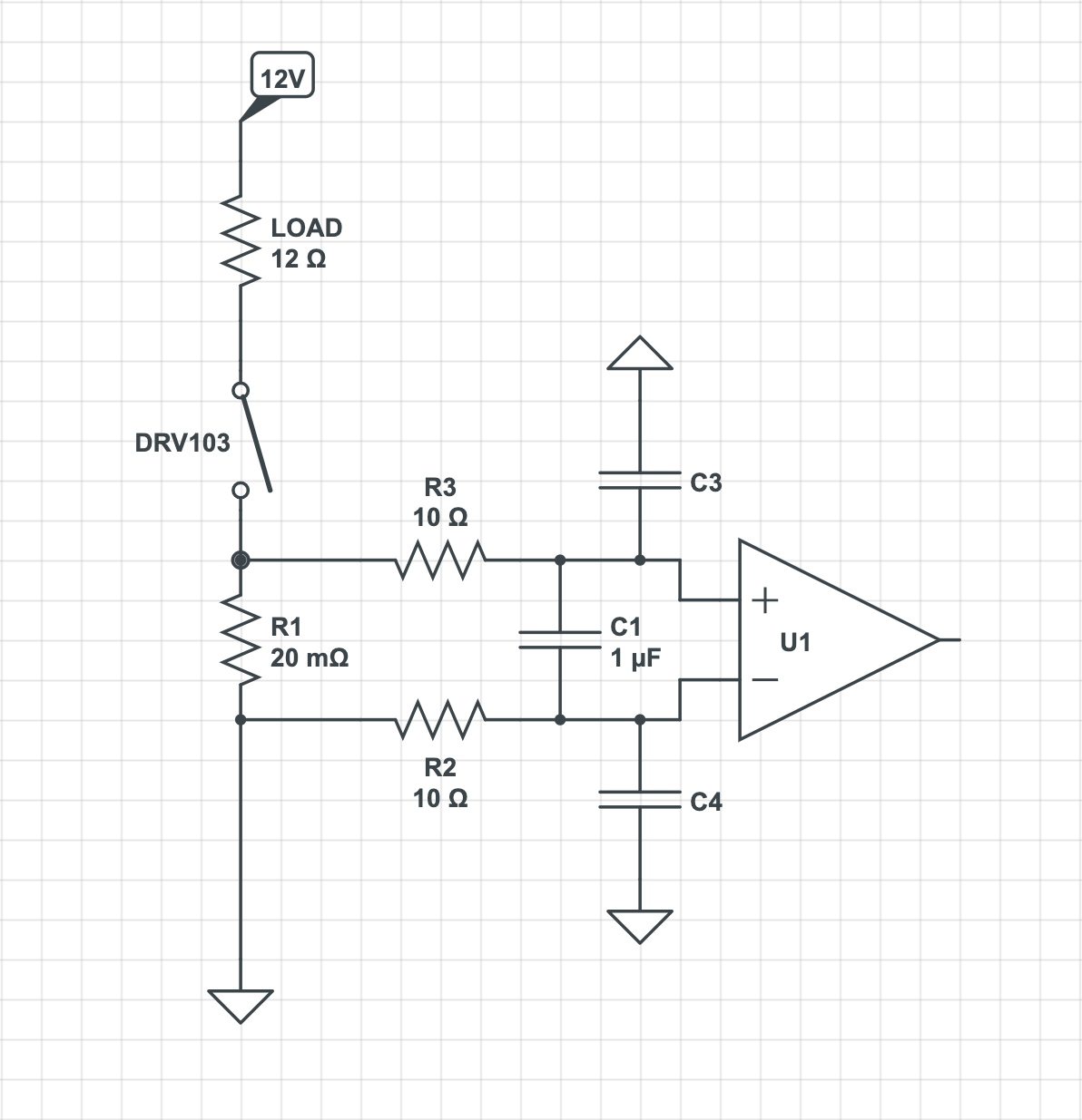
In this proposed layout, the shunt measurement will have much less common-mode noise since it is on the low side of the driver. However, is the DRV103 compatible with this type of layout? I have not seen any DRV103 example circuits where the GND pin is connected to anything but GND. If I did implement this layout, would I need to attach the driver configuration passives to the high side of the shunt for proper operation? What about the heatsink metal pad? Would lowering the shunt resistance to say 10mΩ help, or is this all around just a bad idea to put a shunt between the DRV103 and ground?
Thanks
