This thread has been locked.

If you have a related question, please click the "Ask a related question" button in the top right corner. The newly created question will be automatically linked to this question.

BQ24650: Sense resistor RSR got burned.

Part Number: BQ24650
Other Parts Discussed in Thread: TPS1663, TPS2663, BQ24610

Hi,

We have this recurring issue that for some of our boards the sense resistor got burned even though it is sized correctly.

We are charging a 5-cell LifPO4 battery.

Max charging current is 4A so RSR=10mOhm and rated for 1W.

After it burns, it damages also the BQ24650 so even replacing the RSR will not help.

We have done extensive testing to find out and reproduce this issue and established a theory we would like to share.

The only way to reproduce this issue was to short circuit the mains (Inputs of the adapter). We don't understand why this burns the resistor but it does.

It seems to me that when we short circuit the mains, since the high side MOSFET is on - excessive current will run through the RSR and back to the SRN pin which results in both the RSR and the BQ24650 burning.

1. Will using an eFuse like TPS1663 or TPS2663 can help? If so, where to put it? in series with the RSR or on the mains?

2. Will adding a resistor in series with the SRN pin possible and can protect the circuit? I saw this in the document  "BQ24610_BQ24650_Schematic_Checklist.pdf " as R17. If this is possible, what is the recommended value for that resistor?

3. Another thing that I noticed that is different in our design from the "BQ24610_BQ24650_Schematic_Checklist.pdf is the connection to the system. In the document the system is directly powered from the BQ24650 while charging the battery and when there is no power to the BQ24650, the system is powered from the battery via the D8 diode,

In our system, since the power from the solar charger is too high for the system, we power the system directly from the battery, this results in parallel connection of the battery and the system to the BQ24650 output - the principal schema. Could it be that this kind of connection can hurt the BQ24650 / RSR ?

Note, while running, the system is disconnected from the solar panel and powered only from the battery, it drives 2 BLDC motors up to 15 AMPS. There is no diode between the battery and the BQ24650, only a MOSFET to provide reverse polarity protection, but once it is open, current can flow back from the battery to the BQ24650. Would a diode be recommended?  

See below the schematics and the principal connection scheme:

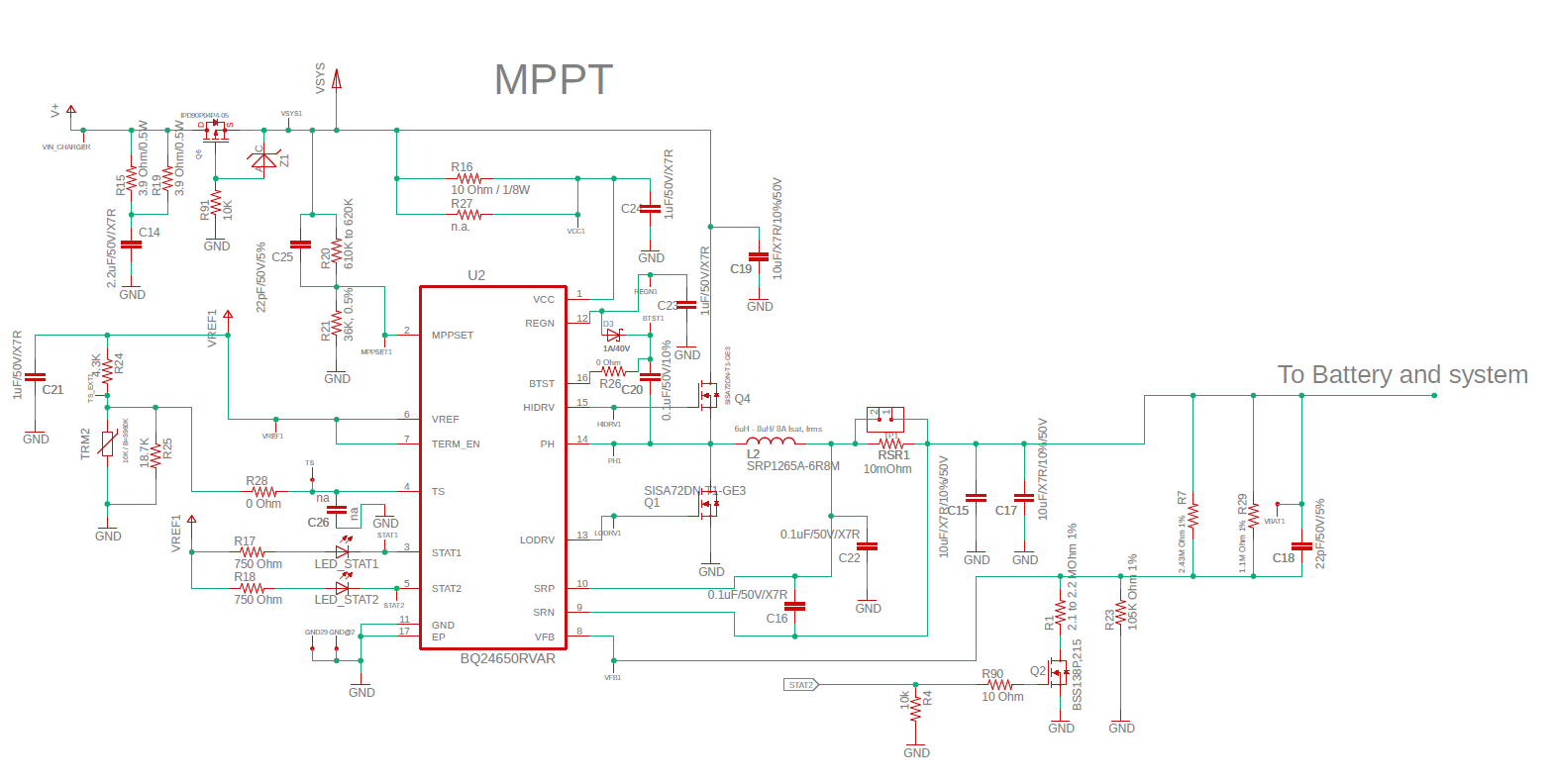
Your help is greatly appreciated,

Best,

Tomer

  • Hi Tomer,

    1. Is the battery providing the system load, while input voltage is connected and battery is charging?
    2. Does the RSR only burn when input mains are shorted? Is there any other condition you observe the RSR and BQ24650 being damaged?
      1. Are you starting up into the input main short, or are you shorting the input mains during charging?   
    3. What is the failure rate you are referring to?
      1. Some boards are damaged when input mains are shorted?
    4. What is reverse breakdown voltage of zener diode at GS of Q6?
      1. How is this PFET controlled? If pulled to GND through the current limit resistor of R91, it will always be on, while the zener just clamps the negative VGS < -VGS max of PFET. This means you are not able to use the input reverse polarity protection of the Q6 body diode.


  • Hi Kedar,

    1. Yes, the battery is the power source of the system at all times. The system is always on, when the motors starts it moves out of the charging dock and the system is powered only by the battery (the BQ circuitry is on board - it just disconnect from the solar panel).

    2. We managed to burn the RSR by sorting the mains but I believe there are other reasons for it to burn because we never observes the actual short on the damaged boards. Since this is a moving system,l we move in and out of a docking station, the docking is comprised of two metallic leads that come in contact with the opposite leads that are connected to the board. These are the mains.
    We saw that during the closing of the contacts - I.E. when the cart returns to the docking there are sparks on the positive lead.

    1. I was shorting during charge not starting up shorted.

    3. About 10 percent. we have 200 boards installed and 20 of them experienced this issue. Again - I am not sure that the mains are actually shorted in the systems on the field, certainly not constantly, but the phenomenon is the same.

    4. 10V - it just to provide VGS < VGS max.

    1. If the polarity is revered then GND becomes (+) and V+ becomes (-) in that case the gate will be pulled to V+ and the PMOS will stay closed. Am I missing something?

    Thanks,

    Tomer

  • Hi Tomer,

      The PFET protects against reverse polarity insertion of the battery or the adapter, however in the event you short your mains (input supply) there is a direct path through the body diode of the HSFET and then through the Q6 FET which would be closed (no body diode of Q6 to provide protection) and the battery would dump as much current back through the RSR, inductor, HSFET body diode, Q6 PFET path. This would exceed the power rating of the RSR as well as possibly damage your HSFET, which at this point is conducting directly through its body diode.. 

    If shorting the mains is a possibility then just having a diode there would protect better, although the downside is the loss in efficiency.

  • Thanks Kedar,

    I understand you r point.

    So, where would you suggest to place the diode? The obvious place is instead of Q6 but will a diode on the power path to the battery is also recommended?

    I understand that in that case, the BQ24650 will not be powered when the solar panel is not connect but that is fine with me.

    Under option that I have in another design is to put back to back PMOS like Q6 - will that be a good option as well or is it the same as the current solution since they will both be on ?

    Thanks,

    Tomer

  • Hi Tomer,

       I would suggest in place of Q6 as this is how we have it on the EVM as well. In your system, there isn't a powerpath as they system is hanging directly off of the battery right? (from the block diagram) On the EVM it connects the SYS directly to the input or battery so that powerpath diode is needed.

    I am not sure what you mean by BQ24650 not powered when no solar panel connected? If the IC doesn't have an input it would not be powered in your current setup as well. This is because we have a SLEEP threshold.

    Yes adding a back to back PFET would not help for the same reason. BQ24610 uses that configuration, but mainly because it has an integrated ACDRV driver that can drive the input reverse blocking FETs.

    Adding a diode in between SRN and your battery could be done as added protection, but note the power dissipation loss would be higher, as in a buck converter the input current < output current, so power loss across input diode would be less than an output diode.

  • Thank you Kedar,

    I think this will resolve my problem.

    I will update the design and if we will encounter this issue again I will start a related thread.

    Thanks again,

    Tomer

  • Hi Kedar,

    One additional thing please,

    Will adding a resistor in series with the SRN pin possible and can protect the circuit? I saw this in the document  "BQ24610_BQ24650_Schematic_Checklist.pdf " as R17. If this is possible, what is the recommended value for that resistor?

    Thanks,

    Tomer

  • Hi Tomer,

       R17 is an optional resistor to add that creates an RC filter at the SRN node. It is not required or recommended as it is an option if there is instability at the SRN node, and adding it will not help to protect the circuit from the issue you are seeing when RSR gets burned..