Hi,
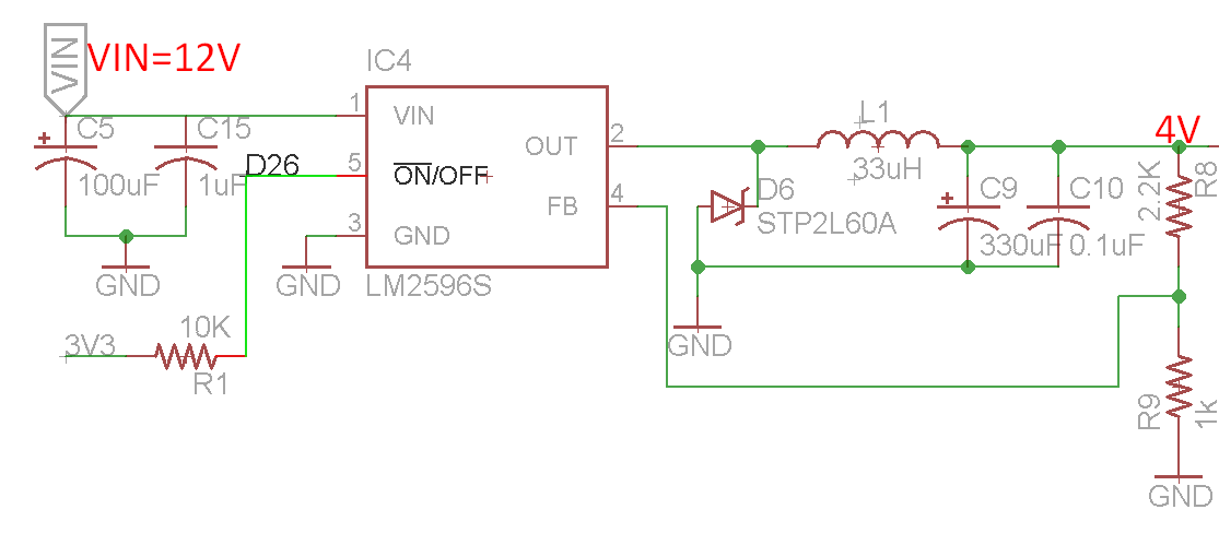
I have a system in which by default I have made the LM2596 regulator OFF. The ON/OFF pin is connected to controller (D26). I have programmed it in such a way that, the regulator (4V) will ON after 2 seconds of turning ON the power supply (VIN=12V). Also, the controller power is independent of LM2596's output power.
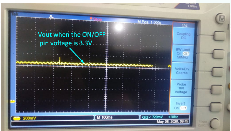
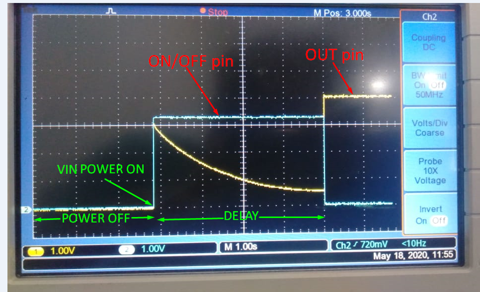
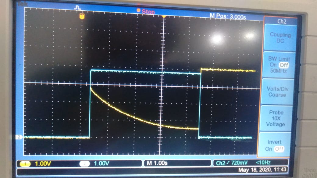
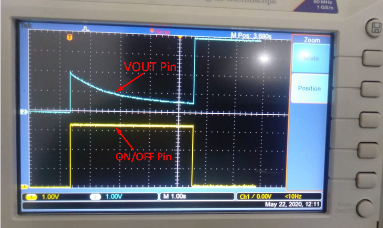
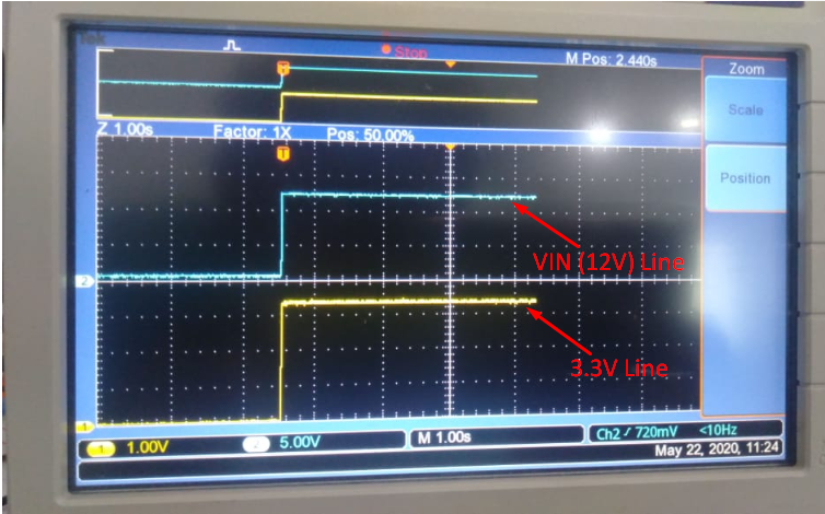
But, When I turn ON the power supply (12V), I have found a overshoot up-to 2V and then a decay for 4 seconds after which the regulator turns ON. The output voltage is fine (4V).

What could be the reason of this overshoot ? Also, I have given a delay of 2 seconds (mentioned earlier), but practically it turns ON after 4 seconds, Why? Please help.