This thread has been locked.

If you have a related question, please click the "Ask a related question" button in the top right corner. The newly created question will be automatically linked to this question.

BQ25101: Reference design for BQ25101

Part Number: BQ25101
Other Parts Discussed in Thread: BQ25155, BQ25150

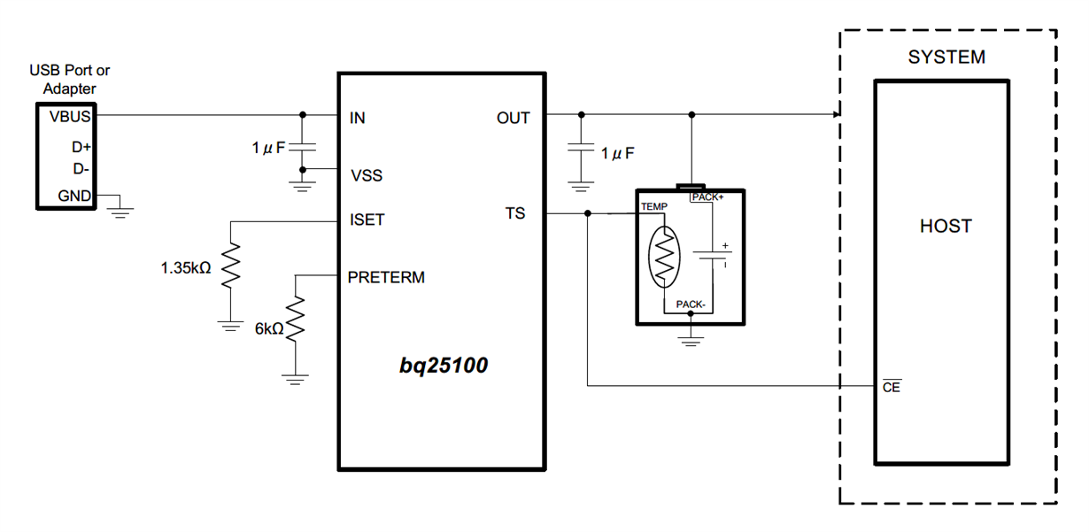
We are using BQ25101 in our design. We implemented the same circuit given in the datasheet as below in the previous version of the PCB, but we had an issue. We couldn't bring up the MCU. The MCU started waking up thru the "battery - OUT (charger) - GPIO(MCU)" connection before the power from the regulator reaches MCU VDDS. When we disconnect the battery to GPIO connection, the issue is resolved. 

We know that we need a switch between the "battery - OUT (charger)" and "MCU GPIO". I cannot find any TI reference design which shows the implementation of BQ25101 to the MCU with a switch. Could you please help to share if you have any?

  • Hi Pragash,

    Does regulator you are using provide a power good (PG) output pin? You could connect the PG pin to the gate of a FET to switch the signal into MCU pin. 

    Best,

  • there is no power good output pin!

  • Pragash,

    What are you trying to achieve by connecting the battery directly to GPIO? We don't often see this as battery voltage can exceed the maximum allowed by the MCU pins. 

    Best,

  • We are trying to measure battery level through GPIO. we are trying to deploy NMOS switch between battery and MCU GPIO. is it feasible this way?

  • Hi Pragash,

    Using an NMOS switch is feasible, issue is that the BQ25101 doesn't have any outputs that could control the switch when needed. Recommend looking for regulator that has a power good output. Another solution would be to use a charger with built in ADC like BQ25155, you could read the battery voltage over I2C.

    Best,

  • We want a low power USB charger Chip which can measure battery level. Could you please suggest one? low power consumption during operation is critical for us. if we can turn off the charger completely after charging (during device operation), it will be the best!

    I have another question on D+ and D-. is it a must for the charger to have D+ and D- line? what if it doesn't have D+ and D-? 

    Based on below datasheet, I know that D+ and D- lines help in autodetection and no transceiver required for charging. If there is no D+ and D- in the charger, does it mean USB transceiver is a must for charging and not all the USB cable can charge the device?

    https://www.ti.com/lit/ds/symlink/bq24050.pdf?&ts=1589442520965

  • We worried I2C pull-ups draws current when the device is not charging, and the I2C is in open-drain mode! Any ways to avoid this? Has any technology overcome this? we also need battery level measurement in the charging chip.

  • Pragash,

    We want a low power USB charger Chip which can measure battery level. Could you please suggest one?

    BQ25155 / BQ25150 are currently our only chargers with built in ADC to support voltage-based gauging. Power consumption for these devices is 460nA in low power mode, 10 nA in ship mode. In ship mode, LDO and ADC are disabled however. Refer to table 7 of the datasheet to see what features are supported in each mode.

    We worried I2C pull-ups draws current when the device is not charging, and the I2C is in open-drain mode!

    Leakage current due to I2C pins for these devices is 1uA with integrated IO supply (1.8V). 


    Best,

  • Thanks for your great suggestions. I'm trying to understand the ship mode. We don't have a mechanical switch. Can we still activate and deactivate ship mode? Ship mode will be beneficial for us since we are using an internal Li-poly battery. Our product which will be shipped must be in the ship mode during air transport. 

  • Pragash,

    Yes, if you want to exit ship mode without mechanical switch we recommend using a FET. MR pin is internally pulled up to VBAT, must be held low for greater than tWAKE1 to exit ship mode. Entering ship mode can be done by setting bit over I2C.

    Best,

  • I have some doubts;

    1) We are a battery-powered device. If MCU program battery charger to enter ship mode, the whole circuit will be turned off, including MCU. Can the program be successfully executed if MCU is going to shut down!

    2) we program the product in the factory into ship mode. When the customer gets it, they have to bring it out of ship mode! Any example of the circuit to accomplish this?  

  • corrected question;

    1) We are a battery-powered device. If MCU program battery charger to enter ship mode, the whole circuit will be turned off, including MCU. Can the program be successfully executed before the MCU goes to shut down!

  • Hi Pragash,


    1) We are a battery-powered device. If MCU program battery charger to enter ship mode, the whole circuit will be turned off, including MCU. Can the program be successfully executed before the MCU goes to shut down! Toggling the low power mode would be practical, ship mode would not be. In low power mode the LDO and BATFET are still enabled.


    2) we program the product in the factory into ship mode. When the customer gets it, they have to bring it out of ship mode! Any example of the circuit to accomplish this? Example can be seen in BQ25155 evm here, using a pushbutton to pull MR pin to ground: 


     Best,