This thread has been locked.

If you have a related question, please click the "Ask a related question" button in the top right corner. The newly created question will be automatically linked to this question.

BQ20Z655-R1: 3.3V LDO regulator

Part Number: BQ20Z655-R1
Other Parts Discussed in Thread: BQ29412

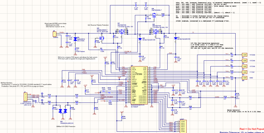
we have a 5 segment LCD connected to the BQ20Z655-R1 with a single 330K on the COM line to the reg33 output. There are no pull-ups on the SEG1-5 lines. On all our 4 cell test validation packs the last battery in the pack (between VC5 and VC4 is discharged lower than the other 3.

Can you tell me what is causing the discharge of this single cell?

The last state of the packs was fully charged and sitting on a shelf.  cell 4-2 are all in the same 3.5V range and cell 1 is in the 2.8-volt range.  Does the reg33 draw only form the last cell in the pack?

  • Hi Tony,

    Could you share the schematic? Thanks.

    Andy

  • The sch is proprietary. I am working with the owner to see what I am allowed to release.

    but I can tell you that the SCH on page 20 of the datasheet was used and is about 90% the same. There is no BQ29412. the LEDs are replaced with a 5 segment LCD and only COM pin 12 has a 330K pull up to the reg33 output. 

  • It really depends on what test was done to it. I'm wondering if you can repeat this test on more packs to see if you can see it again.

  • There was not test. The pack was fully charged and sat on a shelf.

    We came back to it a few months later expecting it to be self discharged. But only the first cell in the pack was low. Not all of them.

    This has happened on both the test packs we built.

  • Hello Tony,

    Can you check the lifetime data from the gg file?

    Could it be your leakage current is too high and that with self-discharge made the battery cell go down to these voltages?

  • If this is a self discharge then why is only cell 1 doing it?

    What I really need to know is where does the BQ draw power to make the 3.3v and 2.5v supplies?  All cells or only cell 1?

  • Hello Tony,

    Tony Brenke15 said:
    If this is a self discharge then why is only cell 1 doing it?

    Yes self discharge is possible, but for similar batch of cells there will be a similar amount of internal self discharge unless one or more of the cells are defective (Outside production controls). It's hard to determine without correlation across multiple battery packs. Can you confirm your observation across multiple packs to establish correlation.

    Tony Brenke15 said:
    What I really need to know is where does the BQ draw power to make the 3.3v and 2.5v supplies?

    As stated in datasheet page 6 & 7, REG25 and REG33 are powered from BAT or VCC. The default power supply is BAT and VCC is a secondary supply option.

    Tony Brenke15 said:
    All cells or only cell 1?

    As mentioned above BAT or VCC, which is the top of the stack.  

  • schematic for the batteries.

    I know self-discharge is a factor. and if this was the case, then all the cells should be low. on the two packs that we have made for testing, it is only cell 1 that is low. down in the 3.2V the other cells are still fully charged.

  • Hello Tony,

    Thanks for sharing the schematic. Can you confirm that all cells were at the same relaxed voltage after charging before observing low voltage on cell 1? Are you using the cell balancing feature of the gauge?

  • Cell balancing, discharge voltage cutoff and over current are why we are using this ic.  The pack was cycled about 5 times and set on a shelf while other projects took center stage. This is when the low cell 1 voltage was found. The pack would not charge until cell 1 was brought back into the range of the others cells outside the BQ charging control with 4.2V at 1.25A.

  • Hello Tony,

    I didn't see anything in the schematic that stands out as odd. Is it possible you have a leaky cap VC5 or some solder flux between VC5 and ASRP? I know it's time consuming to try to reproduce this, but I don't see anything from BQ20Z655 that would cause this behavior internally unless the VC5 go damaged and have a high input leakage. You can measure the voltage across the 100 resistor on VC5 and the other VC4-VC1 to compare if there's significantly higher input leakage on VC5.