This thread has been locked.

If you have a related question, please click the "Ask a related question" button in the top right corner. The newly created question will be automatically linked to this question.

TPS546D24A: How far the romote sense line could get up to?

Part Number: TPS546D24A

Hi there,

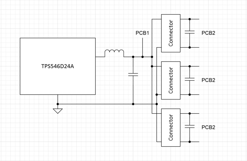
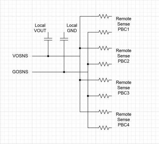
In my application. The output voltage will cross 4 PCB boards and 3 connectors. The distance is about 50cm.  So I want to know, is it OK to connect senseN and senseP to the terminal device. Does the internal conmensation components could make the loop stable. If not. Can I add Op Amp to feedback the senseN and senseP to improve the stability?

The Output voltage range is: 1.2V to 4V

The max current is : 30A

The max output voltage ripple is: +-100mV 

If you have any reference or similar case please let me know.

Best Regards,

Ricardo

  •  

    The limitation of remote sensing for the TPS546D24A, like remote sensing for most power converters, has very little to do with the signal path of the low current remote sense line, and instead is limited by the parasitic delays in the power-path caused by routing inductance and distributed output capacitance.  These parasitic delays can create large phase shifts between the power generation at the output inductor of the TPS546D24A's switching node and the sensed output voltage.  These long delays can limit the bandwidth that the control loop can achieve.

    First, is your system a Parallel system, which each successive PCB drawing power from the prior PCB or a parallel system, with the main PCB having 3 separate connectors, each feeding its own PCB?

    The series case makes for a very complicated remote sense solution since there will be continuously decreasing voltage and increasing delay with each additional connector and board.  The parallel case is a little simpler, but I would still recommend each PCB board having it's own "remote sense" line with a controlled impedance - say 51-ohms for each VOSNS and GOSNS line from each PCB.  The 4 remote sense lines can then be merged into a single remote sense and routed back to the VOSNS and GOSNS pins of the TPS546D24A such that the converter regulated the average voltage on all 4 PCBs.

    To over-come the phase delay from the routing and connector inductance along with the local bypass capacitance on each PCB, you'll want to add a "Feed Forward" capacitor from the output voltage close to the TPS546D24A's output inductor to the VOSNS line after the averaging resistors from each output.  The capacitor's R-C time-constant with the parallel combination of the 4 averaging resistors (51/4 = 12.5) should be less than the L-C time-constant of the power-path routing.

    When routing a remote sense line through a connector, it's always a good idea to make sure there is a local sense line with a higher impedance, 100-1,000 ohms, to make sure there is always a feedback path and the output voltage does not become uncontrolled if the remote sense connection is lost.

    Since the problem with the feedback is not the remote sense line, but the forward power path, adding an Op-Amp buffer to the remote sense is not likely to help.

  • Hi Peter,

    Thanks for your help.

    It's a series system for our application. For some reasons,  PCB 2 and PCB 3 are extend board. The terminal devices are installed on PCB 4. Each TPS546D24A provide power for 32 DUTs, each DUT less than 1A current.

    The routing and connector parasitic inductance and capacitance could be very large. This will make the whole system unstable. As you mentioned that the problem with the feedback is forward power path. Is there any method to increase stability?

    Should we connect the remote sense line to PCB 4 or PCB 1? If the problem is forward power path. It seems like conenct the remote sense line to PCB 4 may not necessary. 

    Regards,

    Ricardo

  •  

    While it is certainly possible to only regulate the voltage at the output connector of PCB 1, PCBs 2, 3, and 4 would suffer from voltage drop due to the losses in the routing and connectors, so you would likely want to increase the voltage at PCB1 closer to the top-end of the allowable range so that the voltage at PCB4 has not dropped as much.

    Another alternative is to mix the voltage on PCB1 with the voltage on PCB4, like I have described above.  the resistive sense lines from PCB4 will help the TPS546D24A automatically raise the voltage on PCB1 so that PCB1 is as much above the target output voltage as PCB4 is below it, while the capacitive feedback from PCB1 helps maintain the high-frequency stability.  It will offer you better performance than just regulating the voltage at PCB 1.

    I would select a time-constant for the R-C feedback network (C = 1 / (2 * Pi * C * F) that is less than is fairly low, likely in the 10kHz range to avoid stability issues being introduced by the remote sense through so much routing and connectors.  It will still be critical that the bypass capacitance on each PCB supports the load transients at least down to that bandwidth, and the routing resistance is low enough to prevent the I-R drop from PCB1 to PCB4 from pulling the DC level out of spec.

    PCB2 and PCB3 will need pass-through connections for the remote sense of PCB 4, and that PBC 1 should have resistive sense to it's output connector and capacitive sense to the capacitor bank right at the output of the TPS546D24A.

    If the design is such that PCB2, PCB3 and PCB4 are identical cards, I would recommend having remote sense resistors on each PCB.  That will still help average the voltage in the feedback, even if it's a weighted average.

  • Hi Peter,

    Thanks for your support.

    I will test this using our EVM board. 

    Regards,

    Ricardo