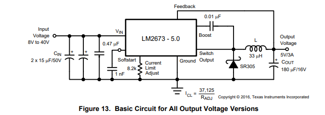
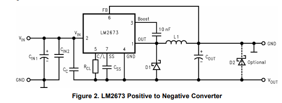
I have a question regarding the LM2673's Current Adjust pin. Below are two different configurations for the LM2673, one to output a positive voltage, and one to output a negative voltage. The regulator has a current limit adjust pin, which limits the peak switch current (current that goes through the inductor) according to the following formula:
Peak Switch Current = 37125 / R_adj.
Now, I've ran some simulations, and I found that given a resistive load at the respective outputs of the circuit, limiting the peak switch current also limits the available output load current by a factor. The positive voltage configuration is approximately a factor of 1.5 whereas the negative voltage configuration appears to be 2.25x. For example, suppose R_adj for the positive voltage circuit is 15k ohms. The peak switch current is 2.475 amps, and the max current that can be delivered to the load is approximately 1.65 amps before voltage starts to drop. This is what I'm seeing in my simulation. As the load current increases, the voltage is maintained at 5 votls up until it tries to draw more than 1.65 amps. After that, the voltage starts to drop. Similarly, in the negative voltage configuration, the voltage will rise as more current is drawn.
I would like to use R_adj as a current limiter of sorts. By using a potentiometer in place of R_adj, I can adjust the peak switch current as needed for my applications. Is this a recommended practice with the LM2673? Are there any concerns/drawbacks of replacing R_adj with an adjustable resistor instead of a fixed value resistor?