This thread has been locked.

If you have a related question, please click the "Ask a related question" button in the top right corner. The newly created question will be automatically linked to this question.

BQ24610: When i pull out the battery ,the system power down (but ADAPTER present) about 30ms

Part Number: BQ24610

Hi TI:

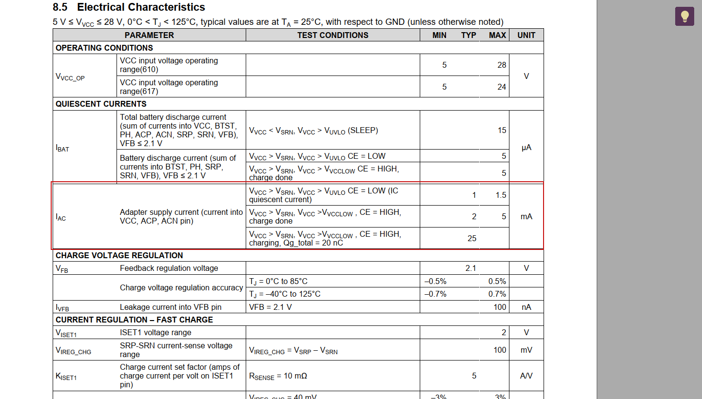
We have a design using BQ24610 , the circuit as same as the 10.2 Typical Application in datesheet (some device is different).

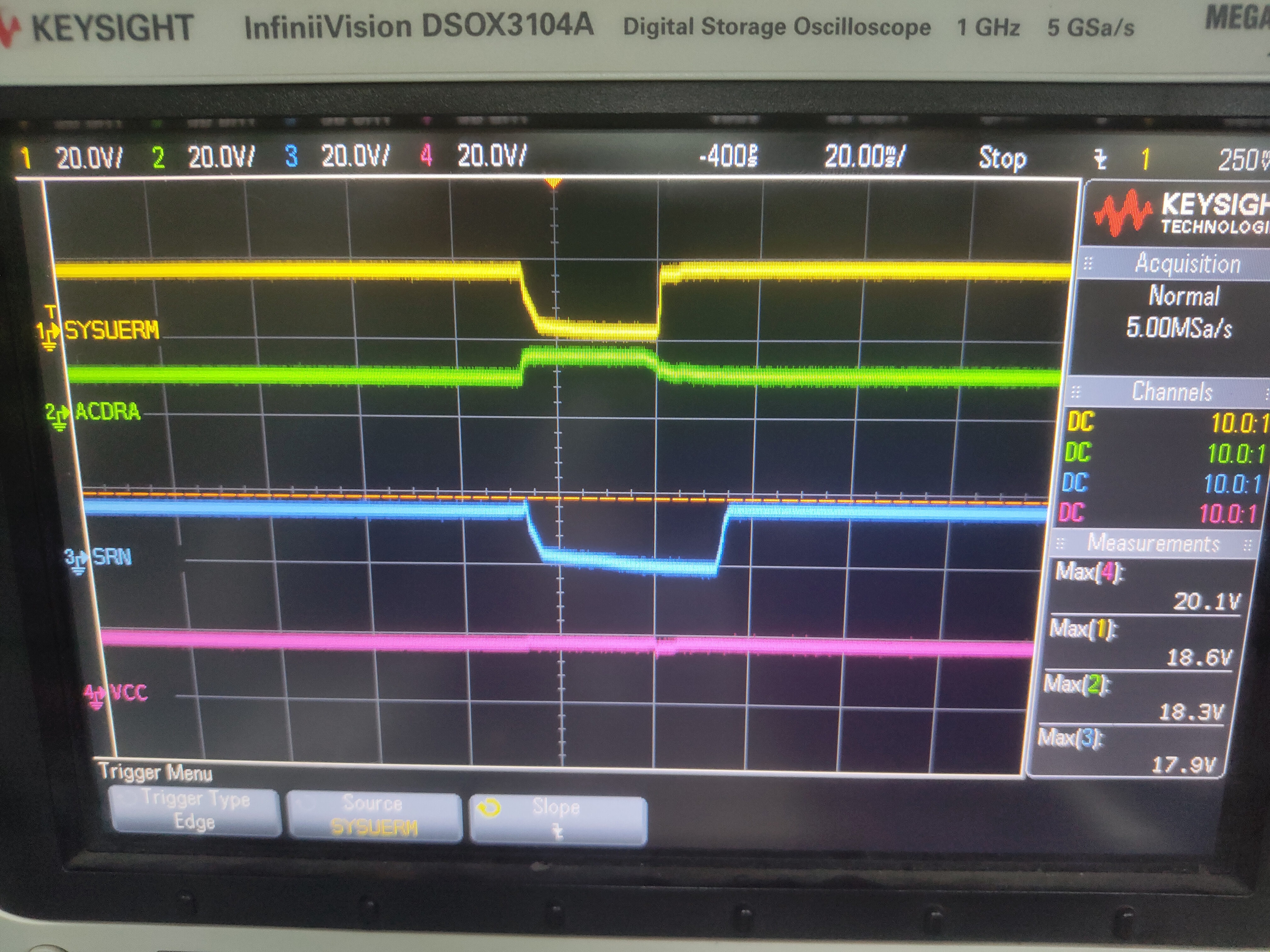
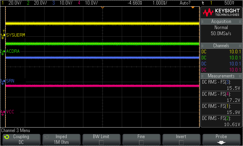
Now we have a problem :I pull out the battery when ADAPTER present (charge in progress) ,in theory,system still can work ,but actually the system power down about 30ms,then it recovery .And i found the ACDRV pull to the voltage of ADAPTER ,so the input mosfet turn off ,  i'm confused about this ,can you help me 

  • Addtionly,the adapter is 19V,the battery is 15.6V.

  • Hi Moon,

        Can you take a scope capture of VSYS, VCC, SRN, ACDRV when battery is unplugged during charging?

  • Hi Kedar:

    This is what happened:

  • Hi Moon,

       The battery is connected to the system by default during power up or during SLEEP mode. The battery is disconnected from the system and then the adapter is connected to the system 30 ms after exiting SLEEP. An automatic break-before-make logic prevents shoot-through currents when the selectors switch.

    Please capture ACDRV BATDRV, SRN, VSYS on one scope capture and ACDRV BATDRV VCC, VSYS on another scope capture. For VCC please monitor close to IC and not actual input supply voltage.

    Please log status of STAT1 and STAT2, and charge current before and after this VSYS dip.

  • Hi Kadar:

    Thanks your reply.


    I think I found the reason:the voltage of SRN will rise to 17.2V when pull out the battery ,and the VCC is close to this ,So the IC enter the SLEEP mode.The spike will sustains 5 ms ,then IC exit the sleep mode .I change the adapter voltage to 19V, no power down happened again .

    Maybe a TVS can make some impact, do you have any advice?

    Regards,

    Moon

  • Hi Moon,

        Please answer below questions regarding system configuration:

    1. What is adapter voltage you are using?
    2. What is charge regulation voltage of BQ24610 set to?

    Do you have the scope capture showing this 5ms sustained spike?

  • Hi Moon,

      Also your response regarding entering SLEEP when battery is removed is what I had suspected. The previous tests I had recommended would show if SLEEP would have been entered, as ACDRV and BATDRV are complementary and would show if SLEEP is causing IC to turn off ACDRV and turn on BATDRV, resulting in this 30ms break before make delay. The VCC-SRN would show if SLEEP is hit.

    I have another theory depending on scope capture showing the 5ms spike as well as the questions regarding system configuration.

  • Hi Kedar ,

    1. I test the both of voltages ,the adapter voltage is actually  17.8V which lower the Standard Voltage ;And the charge regulation voltage of BQ24610 and End-of-charge Voltage of Battery are 16.8V (15.6V is Standard Voltage of Battery in datesheet). 

    2.I have a capture of spike ,maybe useful for you (the spike is actually  1ms ):

    3.I can tell you that the BATMOS will turn on  ,but the scope is using by others.If you need the capture of ACDRV and BATDRV ,I can capture it late.

    4.This is a capture which has average voltage label ,maybe useful for you.

    The wrong information is my fault ,I apologize to you.

    Regards,

    Moon

  • Hi Kedar ,

    I found another way to solve this problem: these is a R17 in 10.2 Typical Application in DS. I try to change the value from 10ohm to 2ohm, it also work well and the power down not happened. 

    I check the datasheet ,the current of VCC is 25mA,so the drop cross the R17 will be 0.25V, the power on it will be 6mW;

    My questions are:

    1)Is change the value from 10ohm to 2ohm  have some bad influence?

    2)In EVM the R17 is 1/4W, is this  necessary?

    Regards,

    Moon

  • Hi Moon,

        VCC is a sense pin with minimal current draw (shown in the EC table), and as this is a charge controller the IC itself does not consume much power. 1/4W rated is not necessary.

    With regards to the VCC 10ohm resistor, it is designed as a low pass filter to filter out noise, and have a clean VCC signal, as well as to slow down dV/dt rise on VCC pin so that VCC pin is not damaged. If you have an input filter circuit (RC) to slow down the rise, as well as slow down gate drive of input reverse blocking FET (EVM schematic with series R in ACDRV path and RC from gate to source should be adequate), then this should be okay to change to 2ohm. One thing is to try and have more headroom between adapter and battery voltage, to avoid getting close to this SLEEP condition. Test out with hot plug of input adapter to make sure this 2ohm VCC resistor is valid, and verify that VCC input leakage is acceptable.

  • Also verify if VCC ripple during switching is affected from adding 2 ohm, and if this is acceptable, as noise coupling depends on layout, and is different board to board.

  • Hi Kedar:

    Thanks for your helpful reply !

    I will do what you suggested  and that's really solve my questions !

    Regards,

    Moon