This thread has been locked.

If you have a related question, please click the "Ask a related question" button in the top right corner. The newly created question will be automatically linked to this question.

TPS61022: enable pin

Part Number: TPS61022
Other Parts Discussed in Thread: TPS61023, TPS61021A

Hello,

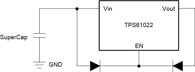
I have selected the TPS61022 for some application due to its low input voltage capability of 0.5V. However, there is an enable pin that requires about 1.2V so that the device can operate. 

is there some solution for that? May be if you please can suggest some other part with very low input voltage and without/with very low enable voltage? I have tried to find one but unable till now.

It would be perfect if it has a spice model that can be simulated using TINA or an unencrypted spice model.

Thank you very much.

Regards,Amr

  • Hi Amr,

    TPS61022 requires a 1.2V for enable pin. May I know your application's detailed information, such as input source voltage range, output voltage, output current range? 

    I'll see if there is a suitable device or a solution.

  • Hi Zack,

    thank you very much for your reply.

    I have checked the datasheet and found the VEN_H of 1.2V and VEN_L of max 0.45V- If I rightly understood, the 1.2V is required only at Startup then if the voltage applied at the enable pin is reduced less than 1.2V, the device keeps powered till the enable pin voltage reaches 0.45V (hysteresis). Could you please confirm/ decline that?

    there is another concern:

    the load I currently connect to the TPS61022 is in most of the cases 50mA or less. At sometimes it increases to about 150mA. In this case, using the webbench, is it advises to set the load current at 150mA and assume 50mA is a light loading condition? Or is it much better to design at the 50mA and assume 150mA a relatively overload condition (still however 150mA very much less than the device rating)? Or to design at some current in between?

    Kind Regards,

    Amr

  • Hi Amr,

    Actually there is no word of hysteresis for the enable pin voltage threshold in TPS61022 datasheet. The VEN_H of 1.2V and VEN_L of 0.45V is a logic level requirement. The enable pin voltage must be higher than 1.2V to enable to device and must be lower than 0.45V to disable to device. A voltage between 0.45V and 1.2V is not promised. 

    Is the input a supercap? What's the output voltage? If your application is a backup power supply, you could connect ENABLE pin to Vout through a pull up resistor.

    TPS61023 is more suitable for your application because the 8A boost converter TPS61022 is overkill for your application.

  • Hello Zack,

    Thank you for the explanations and the suggestions.

    The application is similar to TIDA01385 but the model of TPS61021A didn't function/required an extremely long simulation time  in TINA simulator that's why for checking of the idea of the whole system (by me the system is somehow modified other than TIDA01385), I temporarily moved to TPS61022 because it has an unencypted model that can be used with TINA simulator and it also requires relatively shorter time in the simulation.

    You are right that the TPS61022 is very highly rated than the required specs in my application, and as you recommended, TPS61023 could be much better.

    - With regard to overkilling of the application using the TPS61022, is it due to the very low efficiency at this very light loading condition? 

    - Unfortunately I was unable to find a model for TPS61023 that is compatible with TINA simulator. May I ask you please if there is some model of TPS61023 that can be used with TINA simulator?

    - the EN pin is currently directly connected to Vin. May you please attach some figure to show to pull up to Vout (currently set at 3.3V) while connected to Vin? May be one have to add some resistance between EN and Vin also.

    you are right that the word "hysteresis" is not mentioned in the datasheet. And I was questioning if VH and VL are designed as hysteresis. It is now clear.

    Regards,

    Amr

  • Hi Amr,

    TPS61022 is overkilling because the maximum load is 150mA. So the input average current could be calculated with equation: Iin = Vout * Iout / Vin / Efficiency. Vout=3.6V, Iout=0.15A. The minimum operating input voltage is 0.5V and assume the efficiency is 80%. So Iin = 3.6 * 0.15 / 0.5 /0.8 = 1.35A. TPS61022 switch current limit is 8A and TPS61023 is a low current version with 3.7A switch current limit. 

    Only encrypted spice model for TPS61023 is available on TI.com. Since the control method of these two device are the same. You can use TPS61022 for simulation first.

    Below picture is an example of EN pin connected to Vin and Vout. When the supercap is charged higher than 1.8V (ULVO threshold of TPS61022), TPS61022 starts switching and the left diode conducts. Vout rises to the regulated 3.6V so the right diode conducts. With this connection, even the supercap voltage decharges below 1.2V, the EN pin is still pulled up to Vout.

  • Hello Zack,

    thank you very much for the info. It works.

    However, I noticed that also without adding the diodes that the input voltage at start should be higher than the EN voltage. But during normal operation, if Vin gets lower, it can still get as low as about 0.5 volt before the boost is disabled.

    Below are the waveforms;

    Vcap is the supercap voltage and Voboost is the output of the boost (set at 3.3V however).

    May you please check that. Either the simulation model needs some modifications to cope with the actual performance or the actual performance has some hysteresis.

    Kind Regards,

    Amr

  • Hi Amr,

    That's the feature of TPS61022 and TPS61023. 

    The rising UVLO is 1.8V and falling UVLO is 0.5V. That means TPS61022 needs to start up from 1.8V supercap voltage at least. It is able to regulate the output voltage until supercap discharges to 0.5V. 

  • Hi Zack,

    If I rightly understood, the UVLO assumes that the EN is still set at the 1.2V (through an external supply or whatever). But in the circuit we discuss, the VIN and EN pins are tied together, therefore both Vin and EN reach the 0.5V at the same time. Therefore, I was thinking why the IC isn't shutdown when the EN pin gets less than its 1.2V?

    Regards,

    Amr

  • Hi Amr,

    The EN logic low spec in EC table is 0.35V minimum. The EN logic high spec in EC table is 1.2V maximum. These two value are the key spec in applications. It means if customer would like to enable the device completely, the EN voltage should be higher 1.2V. If customer would like to disable the device completely, the EN voltage should be lower than 0.35V. In another word, if the EN voltage is between these two spec, for example 0.8V, the device is either in active status and shutdown status. 

    That's why in simulation, even the EN pin gets less than 1.2V, the device isn't shutdown.

  • Hi Zack,

    Thanks alot. May be the official name of that isn't hysteresis. But from the simulations it looks exactly like hysteresis. At Startup Vin is less than than the 0.35V and the system is off. Vin still increases getting between the 0.35(0.45V) and the 1.2V but still system off till Vin reaches the 1.2V then the system is enabled. Now if Vin (tied to EN) gets less and going below the 1.2V the system still on till Vin reaches the 0.35-0.45V then the system is off. Isn't this hysteresis? May be there is no need for the diode connection in the previous message?

    Regards,

    Amr

  • Hi Amr,

    The simulation helps customer design the circuit but it's a simplified, ideal model, not a real IC. Please always refer to the Electrical Characteristic Table in datasheet. That's what TI promises. 

    The datasheet has detailed description and explanation about Vin rising and falling UVLO threshold and EN High & Low threshold. Please follow datasheet.

  • Thanks Zack

  • Hi Amr,

    I just double confirmed the EN pin High and Low threshold with our experts. In your case, you can connect EN pin to Vin. Although there is no word of hysteresis in datasheet, but the EN pin low threshold max spec is 0.45V. So there is no problem.

    Please ignore my previous post. Sorry for that.

  • Hello Zack,

    Thank you very much for the info.

    Kind Regards,

    Amr