This thread has been locked.

If you have a related question, please click the "Ask a related question" button in the top right corner. The newly created question will be automatically linked to this question.

TL431: how TL431 start up

Part Number: TL431

Hi,I want to learn how TL431 start up before the Vref get 2.5V in the feedback circuit.

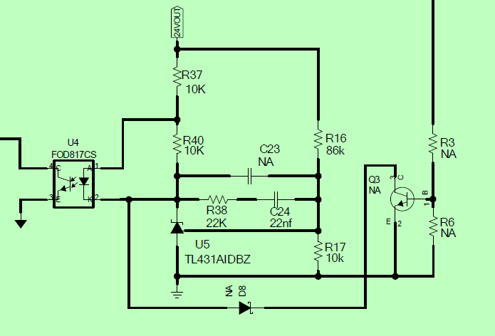
For example, as the pic as below, this is a Flyback SSR circuit with the feedback loop composed of optocoupler and TL431. When we input electrical power, the Flyback circuit start to work, and Vout rises from 0V to 24V. During the startup time, Vref of U5 doesn't get 2.5V,  how much current does the cathode of U5 pull? Can you give me the relationship the current and Vref?

I find that C23/C24/R38 will affect the startup time, so I want to know what happen to TL431 during Vout rise from 0V to 24V. And why  C23/C24/R38 cam affect the startup time?

cathode

  • Hi User,

    I'll get a reference product expert to take a look at this for you after the weekend.

    Thanks,
    Abhinav.

  • The relationship between Ika and Vref is very system specific.  I would look into this app note to know the behavior.

    C23/C24/R38 control the compensation network. A compensation network typically limits the GBW but it gives stability. It slows down the system response rate so that is why adding a compensation network will slow it down.

    I would highly recommend to start with the following app notes to understand more.

  • Hi,Marcoo,thank you for giving me such a lot of informatiom. I will do some tests with different loop compensation parameters to comfirm. I just focus on stability, but neglect GBW. I will share if I have updates

  • Hi, TI engineers,  about the compensation network, I still have some question, and hope you can help me figure it out.

    This is a 12V output power supply. C24=0.1uF, C23=100pF, R38=10k, the output voltage shows as below. After soft-start, the Vout increase very slowly. It takes almost 100ms to start up. Is this because parameter of C24 is too large,  TL431 slew rate become very slow? After soft-start, Vref of TL431 already reaches 2.5V, the compensation starts to work. If after power supply work normally, load changes from no load to heavy load, the output Voltage will fall down to 10V, but still recover to 12V quickly. Why the loop compensation behave differently from start up period to normal working period. That really comfuses me~~

  • Hi,

    That is correct, a larger C24 will limit the bandwidth which will create a much slower response time. The larger C24 will lower the unity gain frequency and thus lower the bandwidth. I would increase the C24 to see where you can get a decent response time and bandwidth.

    While every compensation network is very system specific, I can recommend you to refer to our TL431 reference designs for compensation network examples created by our power designers.

    This design uses 100pF for its C24 equivalent cap which is going to give a much larger bandwidth.

  • Hi, Marcoo Z, about the bandwidth, how large is bandwidth in proper?  I want to know the range of bandwidth in porper. And back to the circuit, In consideration of bandwidth and stabilization, could you please tell me how to set the C24/R38/C23? I already know how to make it have enough gain margin and phase margin, but don't know the range of bandwidth.

  • As per SLUA671 "Generally, 1/5 to 1/10 of switch frequency is preferred as the cross-over frequency." In this case the cross over frequency is the bandwidth you need on the TL431. Section 3 of SLUA671 describes the design much better than I can. Most TI flyback controllers also have their own design rules and examples you can copy to design the compensation network. It is very controller dependent. I would start by looking at what controller you have and what you have available to you.