This thread has been locked.

If you have a related question, please click the "Ask a related question" button in the top right corner. The newly created question will be automatically linked to this question.

UCD3138: Monitor multiple page data on fusion GUI

Part Number: UCD3138

Dear UCD friends,

I'd like to use single UCD3138 to control 2 HSFB power supplies, and hope the fusion GUI can be used to monitor those 2 power supplies data.

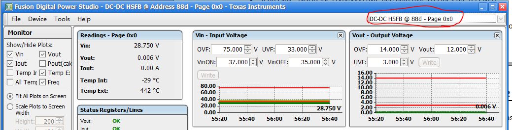
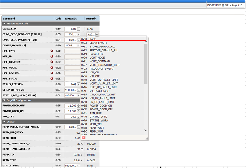
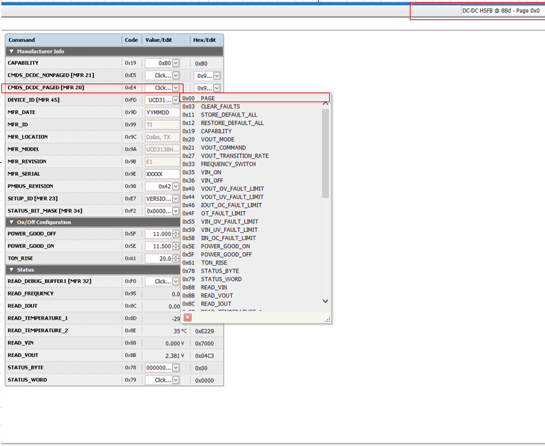
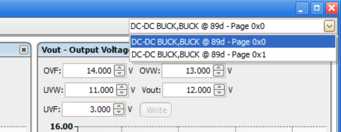
I see the fusion gui will display page 0 at default, can you please help me know how to change it to disaplay data at other pages? Thanks... 

  • Hello Jack,

    As you know, first you need to make some changes to the firmware, in order to accommodate paging support.

    Including the setting of CMD bit mask in order for the GUI to have a way to verify that page command is supported.

    If GUI at the first scanning of the power supply realizes that the power supply supports paging, then the combo box that you have highlighted by a red line drawn around it, will be active. Meaning that the arrow at the right side of the combo box will not be grayed out. And will let you to select the desired page.

    Hope this makes sense.

    Regards,

  • Hi Yizik,

    Thanks for supporting here. And hope everything goes well with you.

    Can you please help me know what exact command has to be added?

    I have viewed the pmbus specification, the page plus write or page plus read command seems can be used in this case, but this is block write or process call protocol, it requries to do some changes to pmbus bottom layer code since current released code didn't support process call. I'm not sure if my understanding is correct. Thanks...  

  • Hello Jack,

    You do not need the page plus command.

    Just the standard PAGE command (CMD CODE-00) is good enough.

    And of course all the other paged commands need to have parameters for both pages now, for example instead of 

    pmbus_dcdc_config.vout_uv_fault_limit you need to have an array of two

    pmbus_dcdc_config[0].vout_uv_fault_limit  and  pmbus_dcdc_config[1].vout_uv_fault_limit  for both pages.

    And as previously mentioned make sure that the CMD bit mask for PAGE CMD is set, so when read command PMBUS_CMD_MFR_CMDS_DCDC_PAGED (0xE4) or read command PMBUS_CMD_MFR_CMDS_DCDC_NONPAGED (0xE5 ) is sent by GUI, GUI will understand that PAGE is supported.

    Regards,

  • Hi Yizik,

    I've tried it on HSFB code which is downloaded from ti website, and implement the page command and set the CMD bit mask for page command. But it's still can't work, can you please share some comments?

    Here are what I've done:

    1. enable the page command in pmbus_topology.h

    #define PMBUS_CMD_00_ENABLE (1)

    2. And related page command code, below code are just for testing purpose, I don't added another pmbus_dcdc_config[1] yet, since I use the same data for 2 pages in current test stage.

    Uint8 page_number = 1;
    Uint8 pmbus_read_page(void)
    {
        pmbus_read_one_byte_handler(page_number);
        return PMBUS_SUCCESS;
    }

    Uint8 pmbus_write_page(void)
    {
        page_number = pmbus_buffer[1];
        return PMBUS_SUCCESS;
    }

    Uint8 pmbus_read_write_page(Uint8 pmbus_read)
    {
        if(pmbus_read)
            return pmbus_read_page();
        else
            return pmbus_write_page();
    }

    3. From the fusion GUI, the page still can't be selected, and always point to page 0x00. And you can see that the PAGE comand bit mask has been set. Thanks...

  • Another test that set the bit mask in CMDS_DCDC_PAGED for page command, page are still can't be selected.

  • Jack,

    I think GUI also checks the SETUP_ID or DEVICE_ID, and if it thinks that the project/EVM has only one PAGE, it does not check the other PAGEs.

    Let me double check this and get back to you (The GUI-GURU is out, this may take some time).

    Regards,

  • Yizik, 

    Thanks. And looking forward to GUI-GURU.

  • Hello Jack,

    The issue was due to the SETUP_ID as I guessed.

    I took the LLC code and replaced the original SETUP_ID with this:

    #define SETUP_ID "20|1V2VNN|BUCK|BUCK"

    and recompiled, that is all. And now the second page shows up in the GUI.


    Sorry the E2E forum does not let me to send you the x0 file.

    Regards,

  • Hi Yizik,

    Thanks for this info.

    One more question, how does the GUI knows how many pages that UCD device support? And what's the prinple of setting the SETUPID? 

  • Hello Jack,

    Your both questions are related.

    The previous SETUP_ID had a format, like this one:

    #define SETUP_ID "20|1V2VNN|BUCK|BUCK"

    1V means that loop/PAGE1 is regulating in voltage mode.

    2V means that loop/PAGE2 is regulating in voltage mode.

    NN means no third loop/PAGE available.

    BUCK|BUCK means the pages are both bucks.

    It was decided to abandon the SETUP_ID with format, the new SETUP_ID is just a name.

    But GUI is backward compatible and supports the old SETUP_IDs.

    GUI does remember the new SETUP_ID for each EVM/Project and it remembers the details of that project including the number of the PAGEs.

    You should either use the above SETUP_ID, or alternatively ask our GUI expert to add your project SETUP_ID to the list of supported projects.

    Regards,

  • Hello Jack,

    Did the above address your concern?

    If so, please set the status of this post to resolved.

    Regards,

  • Hi Yizik,

    Thanks for supporting here. It's resolved. Sorry for late reply.