This thread has been locked.

If you have a related question, please click the "Ask a related question" button in the top right corner. The newly created question will be automatically linked to this question.

TPS63070: Limit of output current with Lithium-ion battery

Part Number: TPS63070

Dear Sir/Madam,

I'm developing a new prototype od portable device, that use a lithium battery (3,7V and 3500mAh) as a main supply.

I'm using the following supply structure to supply the electronic circuit:

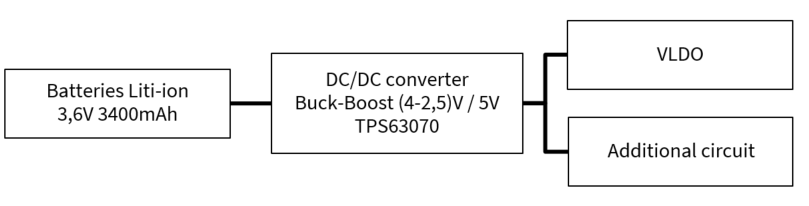
The start-up of circuit works fine and no problem is detected until the connection of additional part of circuit, that is supplied by TPS63070 as the rest of electronic system through the VLDO.
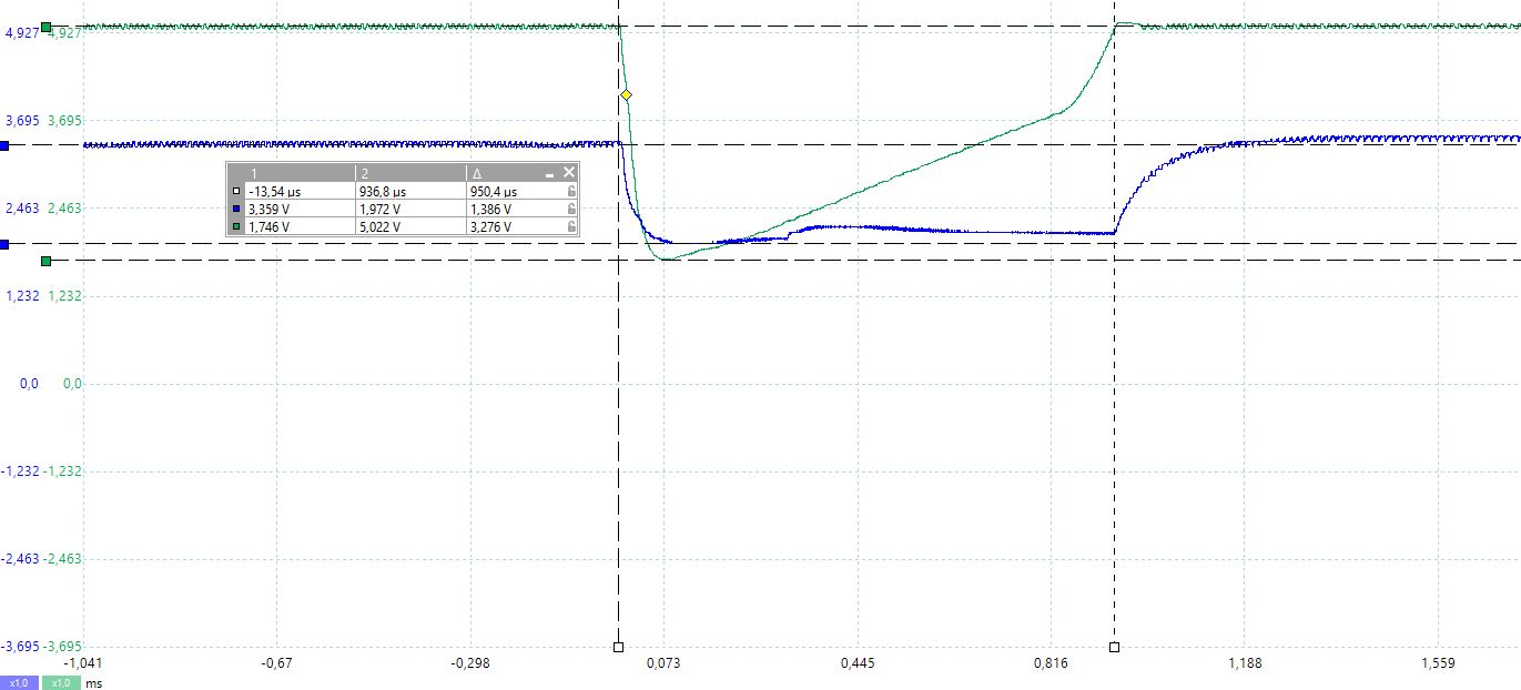
at the time of connection of additional circuit, a high peak current is required and 5V voltage (TPS63070) drops around 2V and the same time the output VLDO, causing functional system error.
I would like to avoid any change in the electronic system and additional part, then I inspected to determine what is the component that limits the current. Is it the batteries that can provide this inrush current or TPS63070 can't give higher current in this operating point?
It quite difficult to access to DC/DC converter output to acquire voltages or current. Hoverver, I have measurements of voltage and current of batteries. please, see the following oscilloscope measurements, could be need more resolution and accuracy but it's possible to take an ideal.

I see some interesting information in the TPS63070 datasheet that allow to calculate an estimation of Iout in TPS63070.
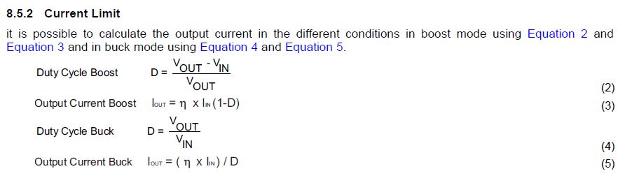
and,

Considering the best case that It's working with 85-95% efficiency, Vout =5V, Vin=3,7V and the input current is around 2A. The result in the boost mode is 1,26-1,4A.

I would like to know if I'm in the right way, and the values says that the converter is in the limit.Hence, this would indicated that is not limitation of battery, that it is right, because the manufacturer indicate more than 4A and limit of 3V for own protection circuit.
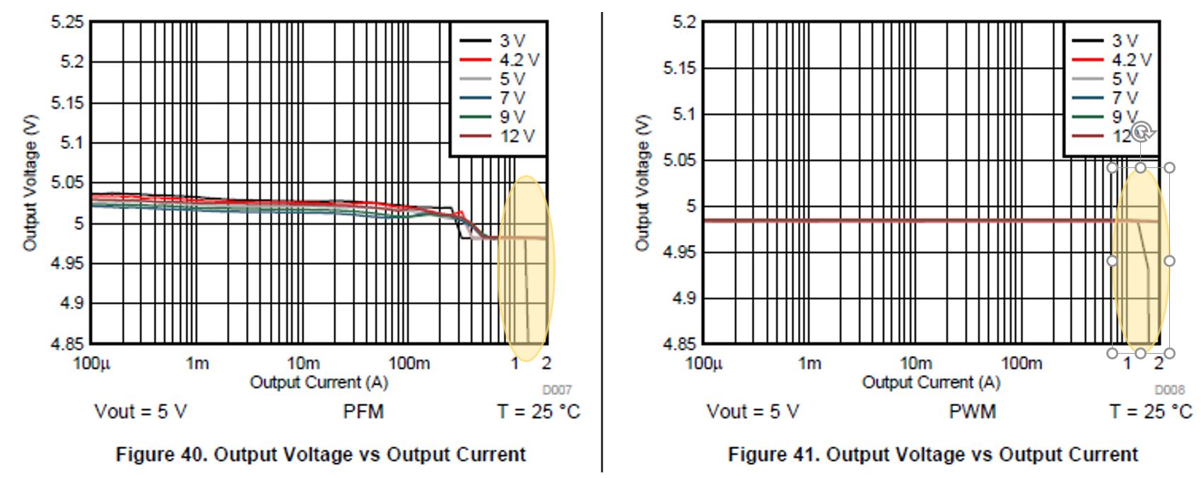
in this case, is the operation point of TPS63070 out of load regulation as the graphs shown?

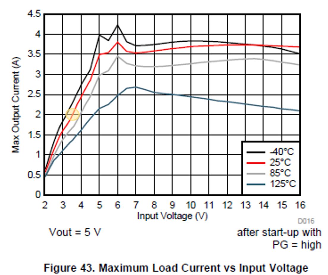
Finally and if I'm not wrong with my hipotesis, I don't understand the next graph of datasheet, where you can though that converter can works with 3,7V to 5V with 2A (the temperature is measured and it's close to environment, 25ºC).

Please, can you help me and solve my doubts?

I have read severals e2e forums about similar issues with TPS63070, but It's not clear for me. Thanks in advance.

Best regards,

  • Hi Robert,

    what is the blue line and yellow line in you waveform? I guess voltage of the battery and current out of the battery, but need conform.

    is the voltage measured closed to the TPS63070 input capacitor? make sure there is no long cable between the real TPS63070 input and the measurement point.

    also try to get a clear waveform of the input voltage, input current and output voltage of the TPS63070

  • Hi Jarper,

    The previous waveforms are just you have commented: (Blue)Lition Baterry Voltage & (Yellow) Lition Baterry Current.

    Please see the following graph. The waveformes shows the voltages of the (blue) input and (green) output voltages, close of the decoupling capacitors.

    The voltage in the input site of TPS63070 is lower because a diode rectifier bridge integrated between battery and converter (voltage drop of 0,5V).

    is the reduction of input voltage around of 2V the reason of drastic drop of 5V output volts?

    I replace the full diode bridge for single diode to reverse voltage protection in order to increase the input voltage os TPS63070. Nevertheless, the result is the same.

    I will be really grateful if you can give some feedback.

    Is It a limitation of DC/DC converter in this working point?

    Thanks in advance

  • Hi Robert,

    sorry for the late reply. 

    i'm thinking maybe the output capacitor is too small. and please disable the power save mode

    could you also share the schematic and layout

  • Hi Jasper,

    Thanks for your reply and support.

    Regarding the schematic, the circuit follow recomendation of datasheet, as you can see in the follow images:

    (Datasheet)

    (My circuit)

    Regarding the save mode, I though that coulb be something related however I not sure because:
    1) The rated consumption of prototype is bettween 200-400mA
    (before peak).
    2) And the change of modes to PWM mode take a very small time and is not appreciated output voltatge drop transient, as the datasheet is explained.

    Moreover, the schematic and layout have fixed mode and I can't change. The reason of this design is the vneed of a low consuption profile.

    Finally, the PCB layout doesn't follow Texas recomendation but I really sure that It is not enough bad to cause this extremly voltage drop.

    Could you give my some recommendation or observation?

    Thanks in advance.

    Keep in touch

  • Sorry the images were not attached.

    (Datasheet)

    (My circuit)

  • Hi Robert,

    i guess this is related to the load transient performance. So i suggested set the device to PWM mode. I was not proposing a solution, just to find the root cause.

    the issue happen "at the time of connection of additional circuit" what is the input capacitor of this additional circuit

  • Hi Robert,

    any update of this case?

  • Hi Jasper,

    The schematic is the same that you can see before. I followed the typical implementation thaty datasheet recommended. This is the reason that I'm really surprised, because I though that It's necessary a bigger output capacitor but the documentation doesn't reflected it.

    I can't share the layout and docuemtnation because part of the project is private, sorry. However, I can say that It's not really good performance when you can see the power supply circuit and distributuin on PCB layout.

    Just a doubt that I have, if we considerate a good implementation in layout follwing the typical circuit of datasheet and recommended layout steps, which is the level of output current that can provide TPS63070 when the input voltage supply is fluctuating bettween 3,5 and 2,2 volts? Can It reach without problems more than 2A?

    In this situation, how fast the DC/DC converter can follow a peak of 3A and 1ms is required in the output circuit? Can I see any parameter in the datasheet that explain the capabilitiy of dI/dt, like "slew rate" in operational amplifier datasheets?

    Thanks for your support

  • Hi Robert,

    the maximum output current depend on the input/output condition. the output current will be low if the input voltage is much small than VOUT.

    the DC/DC switching converter doesn't limit the di/dt ratio, but may not support 3A, which would cause big voltage drop during 1ms.

    I would suggest you apply an EVM for refernece.

  • Hi Robert,

    I closed the post assuming the issue is solved. if not, just reply below