This thread has been locked.

If you have a related question, please click the "Ask a related question" button in the top right corner. The newly created question will be automatically linked to this question.

TPS25926: Need your support for TPS 259261 application

Part Number: TPS25926

Dear sir

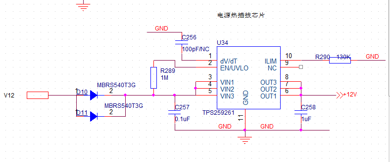
We are using TPS259261  in our product. 

Input Voltage is 12V, and normal load is 1A.

Cout=660uF: we have special purpose for using such big capacitor.

There is no external Cdv/dt.


We've performed power on/off test with 30pcs of product, and found that  10 pcs of TPS259261 were damaged.

Need your support for this issue, what can we do next?

And still some questions for you.

1. How to change the Ramp Time (TdVdT)?

2. What is biggest Ramp Time  we can get by using this chip?

3. What is the biggest Cout can your chip support for 12V@1A load?

4. Per "TPS2592xx Design Calculator.",

" Does Device Enter Current Limit during start-up?" should be false?

"Will the system have glitch-free startup?"   should  be  yes?


BR

Robin


  • Hi Robin,

    Welcome to e2e !

    What is the load current during startup ? The best condition would be startup the efuse with no load and enable the load after startup.

    Below are the answers to your questions,

    1. How to change the Ramp Time (TdVdT)?

    • It changes with Cdvdt. With no dvdt capacitor, the efuse will startup with current limit and hence the startup time depends on the current limit value, output capacitance, Vin (max) and load current during strartup. 

    2. What is biggest Ramp Time  we can get by using this chip?

    • As you add Cdvdt, the ramp rate increases. Theoretically, there is no limit to the maximum ramp rate.

    3. What is the biggest Cout can your chip support for 12V@1A load?

    • It depends on various factors,
      • Vin(max)
      • Load current during startup
      • Maximum Ambient temperature in your system
      • RQJA of the IC on your board (Layout dependent)

    4. Per "TPS2592xx Design Calculator.",

    " Does Device Enter Current Limit during start-up?" should be false?

    • It can  be False or True. It just tells you if the device starts up in current limit or no. If you do not use an external Cdvdt, most probably the device will startup in current limit.

    "Will the system have glitch-free startup?"   should  be  yes?

    • It should be YES to have a successful startup.
    • For your system specification, if you use Cdvdyt = 100nF and if you have no load during stratup then you can have a successful startup.
    • The design calculator gives you a rough idea about startup based on EVM layout. We recommend that you test the startup of the efuse on your board at maximum temperature and with maximum Vin to see if the efuse will have a successful startup.  
  • "What is the load current during startup ? The best condition would be startup the efuse with no load and enable the load after startup."


    How about Cout  capacitors  load? Any recommendation?

    In our application, we must use  Cout as 660uF,  if so ,does it mead we should decrease the In-rush charge current?

    And  let the ramp slew rate as slow as possible?


    And as our  understanding, it has thermal protection  function, but why this chip damaged during power on/off test, which makes me confused. 

    Any other reasons? How to dig it out the root cause? Any suggestions?

    Thanks  a lot.

    BR

    Robin  

  • Hi Robin,

    The efuse has inbuilt thermal protection and it can protect itself during over current, output short circuit and startup conditions.

    When the efuse is turned OFF, there is a sudden drop in current i.e. high di/dt. Inductance in the input path can cause over voltages at the input which are much higher than the Abs Max rating of the device. This is the most common reason for failure of efuse devices. This can be avoided by using a suitable TVS at the input. Similarly -ve voltages can be generated at the output due to inductance in the output path. A schottky diode is needed at the output to clamp -ve voltages.

    As mentioned earlier you can try using a dvdt cap to reduce the inrush current during startup with a huge cap. The key here would be to startup with no load.

  • Hi, Praveen

    1. How to change the Ramp Time (TdVdT)?

    • It changes with Cdvdt. With no dvdt capacitor, the efuse will startup with current limit and hence the startup time depends on the current limit value, output capacitance, Vin (max) and load current during strartup. 

            We set Cdvdt=0.1uF,  and the Vout ramp time is 1s  as measurement. and RIm= 130K ohm,&  Cout=660uF, we performead power on/off test  in charmber @55 degree over 200times, this chip wll not be damaged, we are sure that this failure  triggered by power on step.

            But when we only change the Cdvdt from 0.1uF to 10nf, TPS259261 wll be dameged afer power on/off test at normal temperature, would you please give us some suggestion?

    Also we have another card, Cout=160uF, Rlm=130K, we try to change Cdvdt and performed powered on/off  test, and testing result as below:

    Cdvdt=0.1uf -----> No failure 

    Cdvdt=20nf -----> high failure rate   trigger by power on,

    Cdvdt=39nf -----> high failure rate   failure  trigger by power on

    2. What is biggest Ramp Time  we can get by using this chip?

    • As you add Cdvdt, the ramp rate increases. Theoretically, there is no limit to the maximum ramp rate.

    3. What is the biggest Cout can your chip support for 12V@1A load?

    • It depends on various factors,
      • Vin(max)-------12V
      • Load current during startup--------> 0.2A@12V,  but we are not sure the inrush current.
      • Maximum Ambient temperature in your system------->Failure triggered by power on at normal temperature.
      • RQJA of the IC on your board (Layout dependent)------>Failure triggered by power on at normal temperature, so we can  ignore this ?

    4. Per "TPS2592xx Design Calculator.",

    " Does Device Enter Current Limit during start-up?" should be false?

    • It can  be False or True. It just tells you if the device starts up in current limit or no. If you do not use an external Cdvdt, most probably the device will startup in current limit.

    "Will the system have glitch-free startup?"   should  be  yes?

    • It should be YES to have a successful startup.
    • For your system specification, if you use Cdvdyt = 100nF and if you have no load during stratup then you can have a successful startup.
    • The design calculator gives you a rough idea about startup based on EVM layout. We recommend that you test the startup of the efuse on your board at maximum temperature and with maximum Vin to see if the efuse will have a successful startup.  

  • Please also help to check our sch.

    BR

    Robin

  • We are considering re-spine  of this solution.

    Any other solution for recommendation?

    BR

    Robin 

  • Hi Robin,

    The IC will protect itself as long as the device is operated under Abs Max Rating of the device.

    Most of the efuse failures we see are because of over voltages generated at Input during turn on and during fast-trip conditions due to inductance in the input path. In your schematic, I see there is no TVS at the input to clamp these over voltages. 

    Do you have inductance in the input path in your test setup ? Can you please check the maximum input voltage during turn ON and fast-trip conditions like output short circuit ?

  • Hi,Praveen

    We've measured the waveform, there is no over voltages during start up.

    But when failures occurred, we touched the surface of the chip, it was very very hot.

    This chip introduced into our product   since 2017 without any change.  But recently lot of chip failures happened

     Is it TPS259261 batch issue?  

    BR

    Robin

  • Hi Robin,

    • Can you please elaborate on the condition at which you see failures ?
    • Are the failures on the same board which didn't see any failure from 2017 ?
    • Has there been any changes done on the board ? 
    • Is the schematic shared above your final schematic ? Do you have rough estimate of input and output inductance ?
      • If  there is any significant inductance in the output path, there should be an Schottky diode at the output to clamp for the -ve voltages that can be generated during fast-trip events.


  • Hi, Praveen

    • Can you please elaborate on the condition at which you see failures ?
      • Boards can not powered on, due to chip already damaged. We have to remove the chip, and re-sold it with new one.
    • Are the failures on the same board which didn't see any failure from 2017 ?
      • Yes
    • Has there been any changes done on the board ? 
      • No.
    • Is the schematic shared above your final schematic ? Do you have rough estimate of input and output inductance ?
      • If  there is any significant inductance in the output path, there should be an Schottky diode at the output to clamp for the -ve voltages that can be generated during fast-trip events.
        • No, there i no significant  inductance in the out path.  But however, we have ever  observed  Cout caps failure(shorted).
        • And failure rate is very very low.


  • Hi ,

    Do you mean the device did not power up the first time you applied input voltage and this is when you decided the device is damaged?

  • Hi liuyu,

    If the answer to the above question  is Yes, you will have to contact TI Field applications engineer supporting you to take this issue for debug further.